

Question: Part 2: (40 points) 5. Using the specs in Table 1 below configure Router0 & 1, Switch0, Switch 1, and PCs 0 to 3.
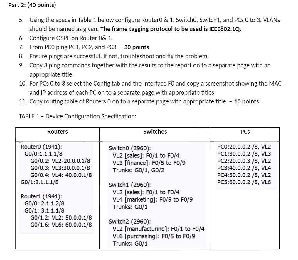
Part 2: (40 points) 5. Using the specs in Table 1 below configure Router0 & 1, Switch0, Switch 1, and PCs 0 to 3. VLANs should be named as given. The frame tagging protocol to be used is IEEE802.1Q. Configure OSPF on Router 0& 1. 6. 7. From PCO ping PC1, PC2, and PC3. - 30 points 8. Ensure pings are successful. If not, troubleshoot and fix the problem. 9. Copy 3 ping commands together with the results to the report on to a separate page with an appropriate title. 10. For PCs 0 to 3 select the Config tab and the Interface FO and copy a screenshot showing the MAC and IP address of each PC on to a separate page with appropriate titles. 11. Copy routing table of Routers 0 on to a separate page with appropriate title. - 10 points TABLE 1- Device Configuration Specification: Routers RouterO (1941): GO/0:1.1.1.1/8 GO/0.2: VL2-20.0.0.1/8 GO/0.3: VL3:30.0.0.1/8 GO/0.4: VL4: 40.0.0.1/8 GO/1:2.1.1.1/8 Router1 (1941): GO/O: 2.1.1.2/8 GO/1: 3.1.1.1/8 GO/1.2: VL2: 50.0.0.1/8 G0/1.6: VL6: 60.0.0.1/8 Switches Switch0 (2960): VL2 [sales]: F0/1 to F0/4 VL3 [finance]: F0/5 to F0/9 Trunks: G0/1, G0/2 Switch1 (2960): VL2 [sales]: F0/1 to F0/4 VL4 [marketing]: F0/5 to F0/9 Trunks: G0/1 Switch2 (2960): VL2 [manufacturing]: F0/1 to F0/4 VL6 [purchasing]: F0/5 to F0/9 Trunks: G0/1 PCs PC0:20.0.0.2 /8, VL2 PC1:30.0.0.2 /8, VL3 PC2:20.0.0.3/8, VL2 PC3:40.0.0.2 /8, VL4 PC4:50.0.0.2 /8, VL2 PC5:60.0.0.2 /8, VL6
Step by Step Solution
There are 3 Steps involved in it

Get step-by-step solutions from verified subject matter experts