

Question: Part 2 : Consider the truss shown below. All connections are pinned ( f e , free to rotate ) See q Page 3 of
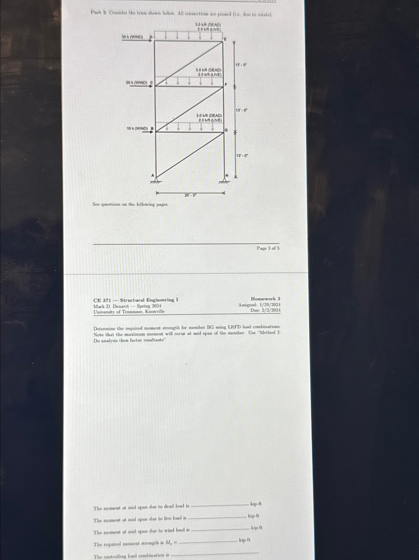
Part : Consider the truss shown below. All connections are pinned f e free to rotate
See q
Page of
CE Structural Engineering I
Mark D Denavit Spring
University of Tennessee, Knoxville
Homework
Asigned:
Due:
Determine the required moment strength for member BG using LRFD load combinations. Note that the maximum moment will occur at mid span of the member. Use "Method Do analysis then factor resultants"
The moment at mid span due to dead load i
kipft
The moment at mid span due to live load is kipft
The moment at mid span due to wind lad is kipft
The required moment streenth is
The controlling load combination is
Step by Step Solution
There are 3 Steps involved in it
1 Expert Approved Answer
Step: 1 Unlock

Question Has Been Solved by an Expert!
Get step-by-step solutions from verified subject matter experts
Step: 2 Unlock
Step: 3 Unlock