

Question: part (B) only Exercise 4.9 In this exercise we examine the operation of the single-cycle datapath for a particu- lar instruction. Problems in this exercise
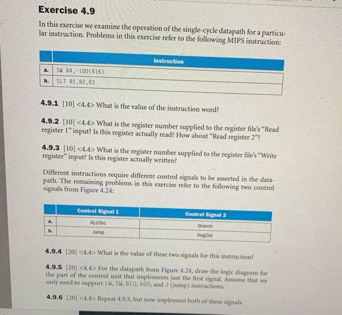
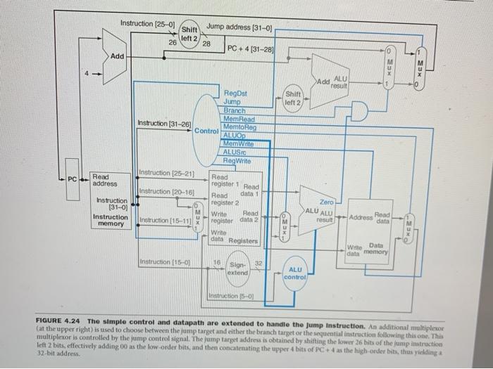
Exercise 4.9 In this exercise we examine the operation of the single-cycle datapath for a particu- lar instruction. Problems in this exercise refer to the following MIPS instruction: Instruction a. SW R4.-100(R16) SLT R1,R2,R3 b. 4.9.1 [10] What is the value of the instruction word? 4.9.2 (10) What is the register number supplied to the register file's Read register 1" input? Is this register actually read? How about Read register 2"? 4.9.3 [10] What is the register number supplied to the register file's "Write register" input? Is this register actually written? Different instructions require different control signals to be asserted in the data- path. The remaining problems in this exercise refer to the following two control signals from Figure 4.24: Control Signal 1 Control Signal 2 ALUS Branch b. Jump Rogost 4.9.4 [20] What is the value of these two signals for this instruction? 4.9.5 [20] For the datapath from Figure 4.24, draw the logic diagram for the part of the control unit that implements just the first signal. Assume that we only need to support LW, SW, BEO, ADD, and J (jump) instructions. 4.9.6 (20) Repeat 4.9.5, but now implement both of these signals. Instruction (25-01 Shift left 2 26 Jump address (31-0) 28 PC +4 [31-28) 4 Add OS - Ado ALU 1 result 0 Shift left 2 RegDst Jump Branch Mem. Read Instruction (31-26] Momto Heg Control ALUOP MomWrite ALUSTO RegWrite instruction [25-21) PC Read address Read Instruction (20-161 register 1 Read data1 Zoro Instruction [31-01 Instruction memory ALU ALU Read register 2 Write Read register data 2 Write Read Instruction (15-111 x Address data result THE 39 dats Register Wie Date data memory Instruction (15-0) 16 Sign 32 extend ALU control Instruction 15-01 FIGURE 4.24 The simple control and datapath are extended to handle the Jump Instruction. An additional multiplier (at the upper right) is used to choose between the jump target and either the branch target or the sequential instruction following this one. This multiplexor is controlled by the jump control signal. The jump target address is obtained by shifting the lower 26 bits of the jump instruction left 2 bits, effectively adding 00 as the low order bits, and then concatenating the upper 4 bits of PC +4 as the high-order bits, thus yieldinga 32-bit address
Step by Step Solution
There are 3 Steps involved in it

Get step-by-step solutions from verified subject matter experts