

Question: PLEASE ANSWER QUESTIONS FROM 1-6 AS ALL ARE A PART OF ONE QUESTION. From atmosphere To atmosphere To help with the analysis follow the steps
 PLEASE ANSWER QUESTIONS FROM 1-6 AS ALL ARE A PART OF ONE QUESTION.
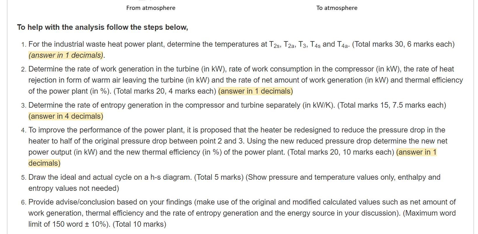
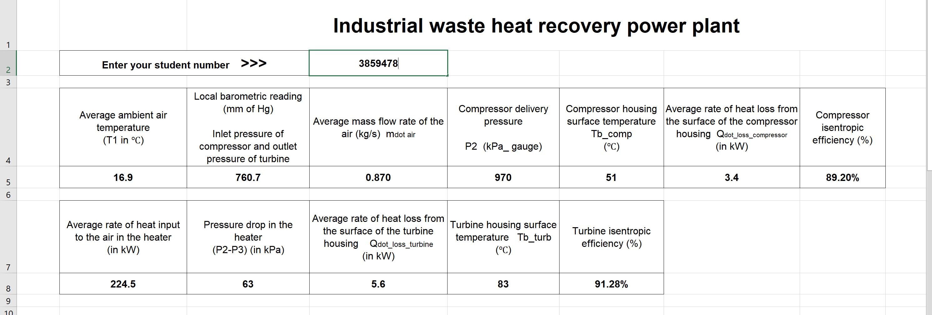
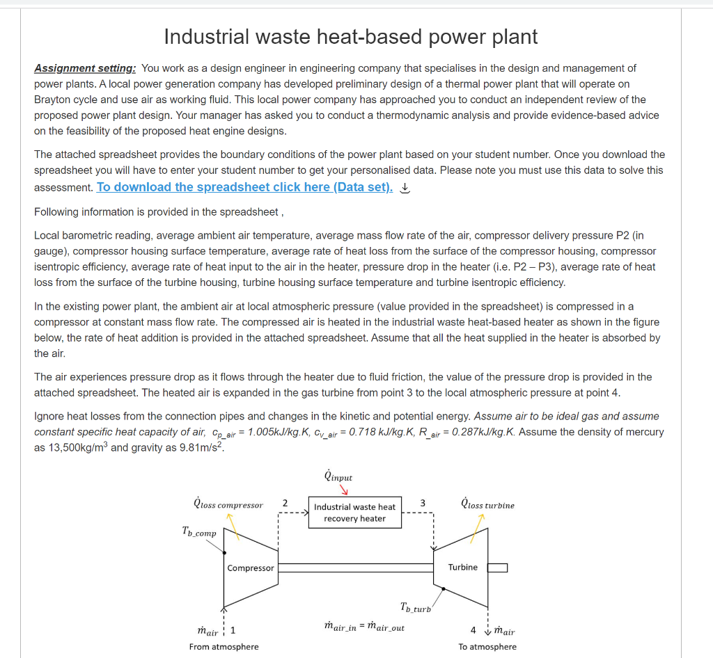
From atmosphere To atmosphere To help with the analysis follow the steps below, 1. For the industrial waste heat power plant, determine the temperatures at T2s, T2, T3, T4s and T4a. (Total marks 30, 6 marks each) (answer in 1 decimals). 2. Determine the rate of work generation in the turbine (in kW), rate of work consumption in the compressor (in kW), the rate of heat rejection in form of warm air leaving the turbine (in kW) and the rate of net amount of work generation (in kW) and thermal efficiency of the power plant (in %). (Total marks 20, 4 marks each) (answer in 1 decimals) 3. Determine the rate of entropy generation in the compressor and turbine separately (in kW/K). (Total marks 15, 7.5 marks each) (answer in 4 decimals) 4. To improve the performance of the power plant, it is proposed that the heater be redesigned to reduce the pressure drop in the heater to half of the original pressure drop between point 2 and 3. Using the new reduced pressure drop determine the new net power output (in kW) and the new thermal efficiency (in %) of the power plant. (Total marks 20, 10 marks each) (answer in 1 decimals) 5. Draw the ideal and actual cycle on a h-s diagram. (Total 5 marks) (Show pressure and temperature values only, enthalpy and entropy values not needed) 6. Provide advise/conclusion based on your findings (make use of the original and modified calculated values such as net amount of work generation, thermal efficiency and the rate of entropy generation and the energy source in your discussion). (Maximum word limit of 150 word + 10%). (Total 10 marks) Industrial waste heat recovery power plant 1 Enter your student number >>> 3859478 2 3 Local barometric reading (mm of Hg) Average ambient air temperature (T1 in C) Average mass flow rate of the air (kg/s) mdot air Compressor delivery pressure Compressor housing Average rate of heat loss from surface temperature the surface of the compressor Tb_comp housing Qdot_loss_compressor (C) (in kW) Compressor isentropic efficiency (%) Inlet pressure of compressor and outlet pressure of turbine P2 (kPa_gauge) 4 16.9 760.7 0.870 970 51 3.4 89.20% 5 6 Average rate of heat input to the air in the heater (in kW) Pressure drop in the heater (P2-P3) (in kPa) Average rate of heat loss from Turbine housing surface the surface of the turbine temperature Tb_turb housing Qdot_loss_turbine (C) (in kW) Turbine isentropic efficiency (%) 7 224.5 63 5.6 83 91.28% 8 9 10 Industrial waste heat-based power plant Assignment setting: You work as a design engineer in engineering company that specialises in the design and management of power plants. A local power generation company has developed preliminary design of a thermal power plant that will operate on Brayton cycle and use air as working fluid. This local power company has approached you to conduct an independent review of the proposed power plant design. Your manager has asked you to conduct a thermodynamic analysis and provide evidence-based advice on the feasibility of the proposed heat engine designs. The attached spreadsheet provides the boundary conditions of the power plant based on your student number. Once you download the spreadsheet you will have to enter your student number to get your personalised data. Please note you must use this data to solve this assessment. To download the spreadsheet click here (Data set). Following information is provided in the spreadsheet, Local barometric reading, average ambient air temperature, average mass flow rate of the air, compressor delivery pressure P2 (in gauge), compressor housing surface temperature, average rate of heat loss from the surface of the compressor housing, compressor isentropic efficiency, average rate of heat input to the air in the heater, pressure drop in the heater (i.e. P2 - P3), average rate of heat loss from the surface of the turbine housing, turbine housing surface temperature and turbine isentropic efficiency. In the existing power plant, the ambient air at local atmospheric pressure (value provided in the spreadsheet) is compressed in a compressor at constant mass flow rate. The compressed air is heated in the industrial waste eat-based ater as shown in the figure below, the rate of heat addition is provided in the attached spreadsheet. Assume that all the heat supplied in the heater is absorbed by the air. The air experiences pressure drop as it flows through the heater due to fluid friction, the value of the pressure drop is provided in the attached spreadsheet. The heated air is expanded in the gas turbine from point 3 to the local atmospheric pressure at point 4. Ignore heat losses from the connection pipes and changes in the kinetic and potential energy. Assume air to be ideal gas and assume constant specific heat capacity of air, Cp_air = 1.005kJ/kg.K, Cy_air = 0.718 kJ/kg.K, R_air = 0.287kJ/kg.K. Assume the density of mercury as 13,500kg/m3 and gravity as 9.81m/s2. Qinput Qloss compressor 2 3 loss turbine Industrial waste heat recovery heater Ty_comp Compressor Turbine To turb mair in = mair_out mair: 1 From atmosphere 4 mair To atmosphere You can use either of the following format of equations to show the calculations (k-1) T1/T2 = (V2N1)^(k-1) / ) OR T1 T2 = (k-1)/k T1/T2 = (P1/P2)^((k-1)/k) OR Ti T2 - P1 P2 (PLEASE DELETE THIS TEXT BOX BEFORE YOU SUBMIT YOUR SOLUTION) From atmosphere To atmosphere To help with the analysis follow the steps below, 1. For the industrial waste heat power plant, determine the temperatures at T2s, T2, T3, T4s and T4a. (Total marks 30, 6 marks each) (answer in 1 decimals). 2. Determine the rate of work generation in the turbine (in kW), rate of work consumption in the compressor (in kW), the rate of heat rejection in form of warm air leaving the turbine (in kW) and the rate of net amount of work generation (in kW) and thermal efficiency of the power plant (in %). (Total marks 20, 4 marks each) (answer in 1 decimals) 3. Determine the rate of entropy generation in the compressor and turbine separately (in kW/K). (Total marks 15, 7.5 marks each) (answer in 4 decimals) 4. To improve the performance of the power plant, it is proposed that the heater be redesigned to reduce the pressure drop in the heater to half of the original pressure drop between point 2 and 3. Using the new reduced pressure drop determine the new net power output (in kW) and the new thermal efficiency (in %) of the power plant. (Total marks 20, 10 marks each) (answer in 1 decimals) 5. Draw the ideal and actual cycle on a h-s diagram. (Total 5 marks) (Show pressure and temperature values only, enthalpy and entropy values not needed) 6. Provide advise/conclusion based on your findings (make use of the original and modified calculated values such as net amount of work generation, thermal efficiency and the rate of entropy generation and the energy source in your discussion). (Maximum word limit of 150 word + 10%). (Total 10 marks) Industrial waste heat recovery power plant 1 Enter your student number >>> 3859478 2 3 Local barometric reading (mm of Hg) Average ambient air temperature (T1 in C) Average mass flow rate of the air (kg/s) mdot air Compressor delivery pressure Compressor housing Average rate of heat loss from surface temperature the surface of the compressor Tb_comp housing Qdot_loss_compressor (C) (in kW) Compressor isentropic efficiency (%) Inlet pressure of compressor and outlet pressure of turbine P2 (kPa_gauge) 4 16.9 760.7 0.870 970 51 3.4 89.20% 5 6 Average rate of heat input to the air in the heater (in kW) Pressure drop in the heater (P2-P3) (in kPa) Average rate of heat loss from Turbine housing surface the surface of the turbine temperature Tb_turb housing Qdot_loss_turbine (C) (in kW) Turbine isentropic efficiency (%) 7 224.5 63 5.6 83 91.28% 8 9 10 Industrial waste heat-based power plant Assignment setting: You work as a design engineer in engineering company that specialises in the design and management of power plants. A local power generation company has developed preliminary design of a thermal power plant that will operate on Brayton cycle and use air as working fluid. This local power company has approached you to conduct an independent review of the proposed power plant design. Your manager has asked you to conduct a thermodynamic analysis and provide evidence-based advice on the feasibility of the proposed heat engine designs. The attached spreadsheet provides the boundary conditions of the power plant based on your student number. Once you download the spreadsheet you will have to enter your student number to get your personalised data. Please note you must use this data to solve this assessment. To download the spreadsheet click here (Data set). Following information is provided in the spreadsheet, Local barometric reading, average ambient air temperature, average mass flow rate of the air, compressor delivery pressure P2 (in gauge), compressor housing surface temperature, average rate of heat loss from the surface of the compressor housing, compressor isentropic efficiency, average rate of heat input to the air in the heater, pressure drop in the heater (i.e. P2 - P3), average rate of heat loss from the surface of the turbine housing, turbine housing surface temperature and turbine isentropic efficiency. In the existing power plant, the ambient air at local atmospheric pressure (value provided in the spreadsheet) is compressed in a compressor at constant mass flow rate. The compressed air is heated in the industrial waste eat-based ater as shown in the figure below, the rate of heat addition is provided in the attached spreadsheet. Assume that all the heat supplied in the heater is absorbed by the air. The air experiences pressure drop as it flows through the heater due to fluid friction, the value of the pressure drop is provided in the attached spreadsheet. The heated air is expanded in the gas turbine from point 3 to the local atmospheric pressure at point 4. Ignore heat losses from the connection pipes and changes in the kinetic and potential energy. Assume air to be ideal gas and assume constant specific heat capacity of air, Cp_air = 1.005kJ/kg.K, Cy_air = 0.718 kJ/kg.K, R_air = 0.287kJ/kg.K. Assume the density of mercury as 13,500kg/m3 and gravity as 9.81m/s2. Qinput Qloss compressor 2 3 loss turbine Industrial waste heat recovery heater Ty_comp Compressor Turbine To turb mair in = mair_out mair: 1 From atmosphere 4 mair To atmosphere You can use either of the following format of equations to show the calculations (k-1) T1/T2 = (V2N1)^(k-1) / ) OR T1 T2 = (k-1)/k T1/T2 = (P1/P2)^((k-1)/k) OR Ti T2 - P1 P2 (PLEASE DELETE THIS TEXT BOX BEFORE YOU SUBMIT YOUR SOLUTION)
Step by Step Solution
There are 3 Steps involved in it

Get step-by-step solutions from verified subject matter experts