

Question: Question 1 What do you think this logic buffer gate will do, with the output signal feeding back to the input? Question 2 What
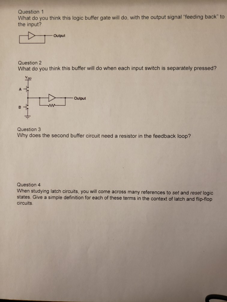
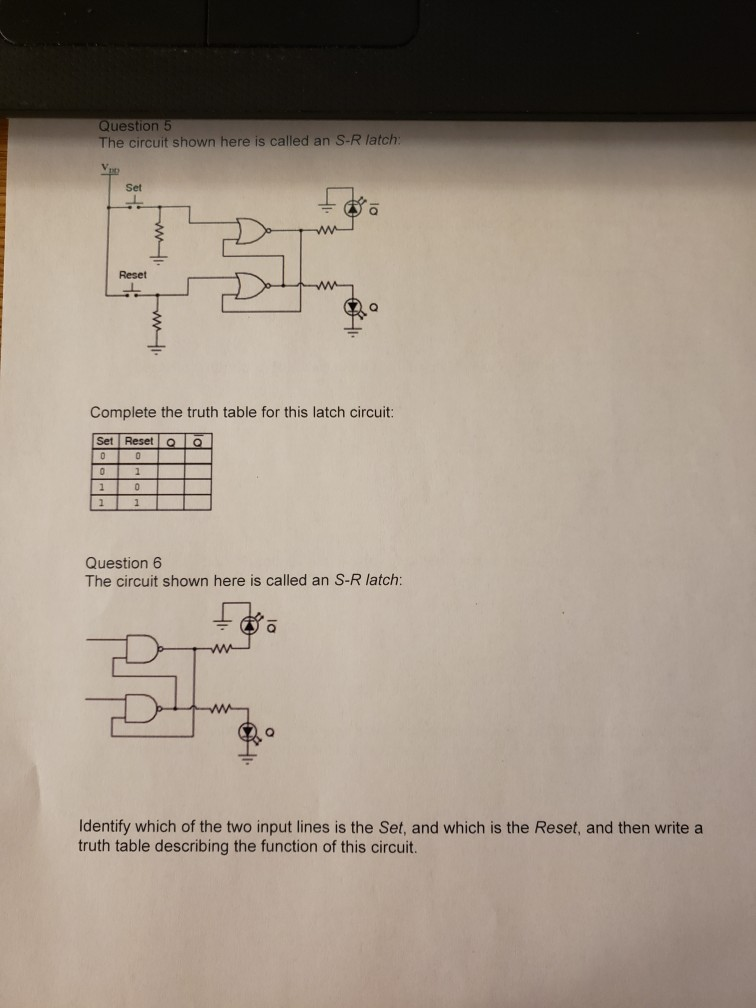
Question 1 What do you think this logic buffer gate will do, with the output signal "feeding back" to the input? Question 2 What do you think this buffer will do when each input switch is separately pressed? A B Output VpD www Output Question 3 Why does the second buffer circuit need a resistor in the feedback loop? Question 4 When studying latch circuits, you will come across many references to set and reset logic states. Give a simple definition for each of these terms in the context of latch and flip-flop circuits. Question 5 The circuit shown here is called an S-R latch: Vp Set 1 1 Reset Complete the truth table for this latch circuit: Set Reset o 0 0 0 1 0 1 www P = Question 6 The circuit shown here is called an S-R latch: Identify which of the two input lines is the Set, and which is the Reset, and then write a truth table describing the function of this circuit.
Step by Step Solution
There are 3 Steps involved in it

Get step-by-step solutions from verified subject matter experts