

Question: A Schmitt Trigger circuit shown in figure 2 is employed in a switching circuit in which Vsat = 10 V, Voc = 2 V,
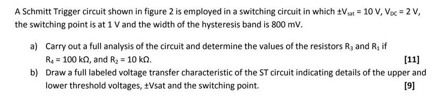
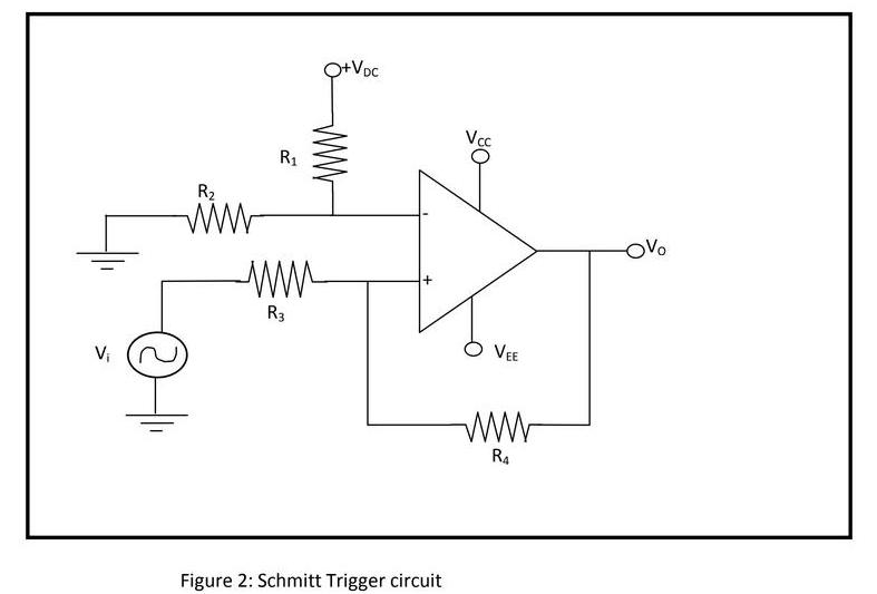
A Schmitt Trigger circuit shown in figure 2 is employed in a switching circuit in which Vsat = 10 V, Voc = 2 V, %3D the switching point is at 1 V and the width of the hysteresis band is 800 mv. a) Carry out a full analysis of the circuit and determine the values of the resistors R3 and R, if R4 = 100 kn, and R2 = 10 kn. [11] %3! b) Draw a full labeled voltage transfer characteristic of the ST circuit indicating details of the upper and lower threshold voltages, Vsat and the switching point. [9] Q+Voc R1 R2 OVo R3 VEE V, R4 Figure 2: Schmitt Trigger circuit wWw
Step by Step Solution
3.51 Rating (151 Votes )
There are 3 Steps involved in it
APCO Date Page I Vset lov Voc 2 2 V Hysteresns oid the f0om v Voc 2v ... View full answer

Get step-by-step solutions from verified subject matter experts