

Question: Please code this in MATLAB ----------------- In Problem 03 transfer functions for a buck converter using a time-averaging approach were used to simulate the converter
Please code this in MATLAB
-----------------
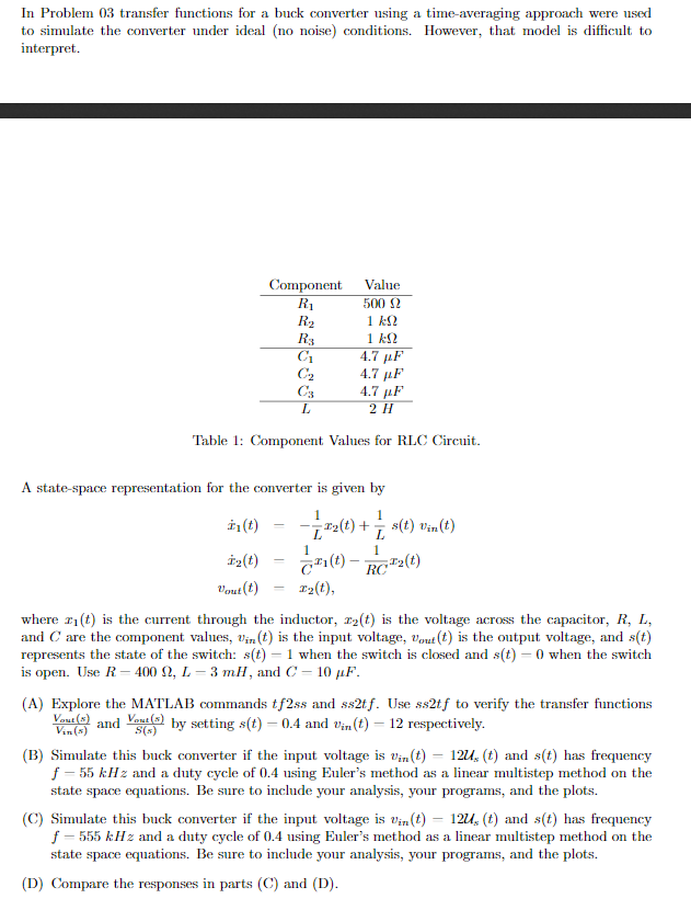
In Problem 03 transfer functions for a buck converter using a time-averaging approach were used to simulate the converter under ideal (no noise) conditions. However, that model is difficult to interpret. Component R2 Value 500 12 1 k12 1 22 4.7 F 4.7 MF 4.7 F 2 H Table 1: Component Values for RLC Circuit. A state-space representation for the converter is given by (t) = 2(t) + s(t) vin(t) (t) = c(t) - RC=2(t) Vout(t) = 12t), where wit) is the current through the inductor, 22(t) is the voltage across the capacitor, R, L, and C are the component values, Vin (t) is the input voltage, Yout(t) is the output voltage, and s(t) represents the state of the switch: s(t) 1 when the switch is closed and st) - 0 when the switch is open. Use R-400 12, L-3 mH, and C - 10 uF. (A) Explore the MATLAB commands tf2ss and ss2tf. Use ss2tf to verify the transfer functions Vous and set by setting s(t) = 0.4 and Vin(t) = 12 respectively. (B) Simulate this buck converter if the input voltage is Vin(t) = 120, (t) and s(t) has frequency f -55 kHz and a duty cycle of 0.4 using Euler's method as a linear multistep method on the state space equations. Be sure to include your analysis, your programs, and the plots. (C) Simulate this buck converter if the input voltage is Vin(t) = 120; (t) and s(t) has frequency f - 555 kHz and a duty cycle of 0.4 using Euler's method as a linear multistep method on the state space equations. Be sure to include your analysis, your programs, and the plots. (D) Compare the responses in parts (C) and (D). In Problem 03 transfer functions for a buck converter using a time-averaging approach were used to simulate the converter under ideal (no noise) conditions. However, that model is difficult to interpret. Component R2 Value 500 12 1 k12 1 22 4.7 F 4.7 MF 4.7 F 2 H Table 1: Component Values for RLC Circuit. A state-space representation for the converter is given by (t) = 2(t) + s(t) vin(t) (t) = c(t) - RC=2(t) Vout(t) = 12t), where wit) is the current through the inductor, 22(t) is the voltage across the capacitor, R, L, and C are the component values, Vin (t) is the input voltage, Yout(t) is the output voltage, and s(t) represents the state of the switch: s(t) 1 when the switch is closed and st) - 0 when the switch is open. Use R-400 12, L-3 mH, and C - 10 uF. (A) Explore the MATLAB commands tf2ss and ss2tf. Use ss2tf to verify the transfer functions Vous and set by setting s(t) = 0.4 and Vin(t) = 12 respectively. (B) Simulate this buck converter if the input voltage is Vin(t) = 120, (t) and s(t) has frequency f -55 kHz and a duty cycle of 0.4 using Euler's method as a linear multistep method on the state space equations. Be sure to include your analysis, your programs, and the plots. (C) Simulate this buck converter if the input voltage is Vin(t) = 120; (t) and s(t) has frequency f - 555 kHz and a duty cycle of 0.4 using Euler's method as a linear multistep method on the state space equations. Be sure to include your analysis, your programs, and the plots. (D) Compare the responses in parts (C) and (D)
Step by Step Solution
There are 3 Steps involved in it

Get step-by-step solutions from verified subject matter experts