

Question: Please do the simulation. 1 Objective DRIVER The objective in this project is to design an LED Driver using chip on board ( COB )
Please do the simulation.
Objective
DRIVER
The objective in this project is to design an LED Driver using chip on board COB or PCB power
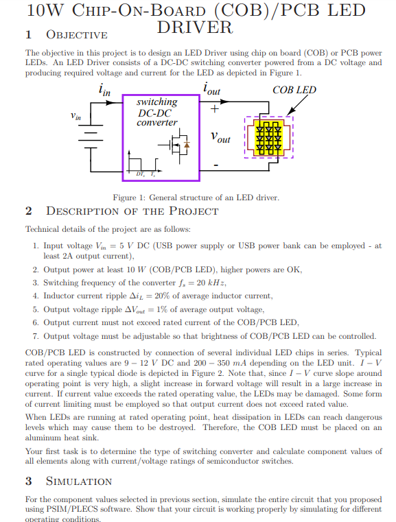
LEDs. An LED Driver consists of a DCDC switching converter powered from a DC voltage and
producing required voltage and current for the LED as depicted in Figure
Figure : General structure of an LED driver.
Description of the Project
Technical details of the project are as follows:
Input voltage VinV DC USB power supply or USB power bank can be employed at
least A output current
Output power at least W COBPCB LED higher powers are OK
Switching frequency of the converter fskHz
Inductor current ripple DeltaiL of average inductor current,
Output voltage ripple DeltaVout of average output voltage,
Output current must not exceed rated current of the COBPCB LED,
Output voltage must be adjustable so that brightness of COBPCB LED can be controlled.
COBPCB LED is constructed by connection of several individual LED chips in series. Typical
rated operating values are V DC and mA depending on the LED unit. IV
curve for a single typical diode is depicted in Figure Note that, since IV curve slope around
operating point is very high, a slight increase in forward voltage will result in a large increase in
current. If current value exceeds the rated operating value, the LEDs may be damaged. Some form
of current limiting must be employed so that output current does not exceed rated value.
When LEDs are running at rated operating point, heat dissipation in LEDs can reach dangerous
levels which may cause them to be destroyed. Therefore, the COB LED must be placed on an
aluminum heat sink.
Your first task is to determine the type of switching converter and calculate component values of
all elements along with currentvoltage ratings of semiconductor switches.
Simulation
For the component values selected in previous section, simulate the entire circuit that you proposed
using PSIMPLECS software. Show that your circuit is working properly by simulating for different
Step by Step Solution
There are 3 Steps involved in it
1 Expert Approved Answer
Step: 1 Unlock

Question Has Been Solved by an Expert!
Get step-by-step solutions from verified subject matter experts
Step: 2 Unlock
Step: 3 Unlock