

Question: The Aux output of an audio device such as a CD player or tape recorder is specified by 500-mV peak voltage and 60-Ohm internal
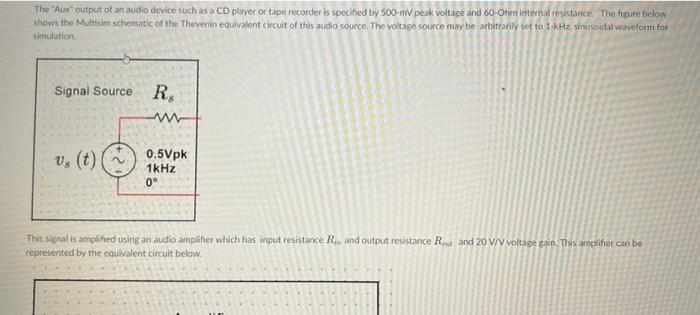
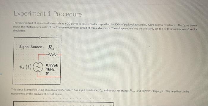
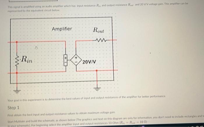
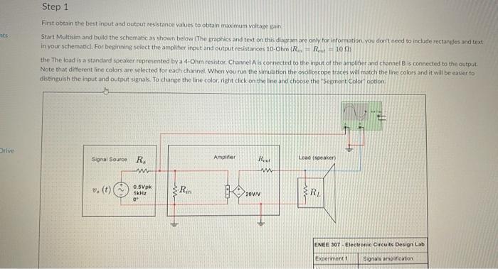
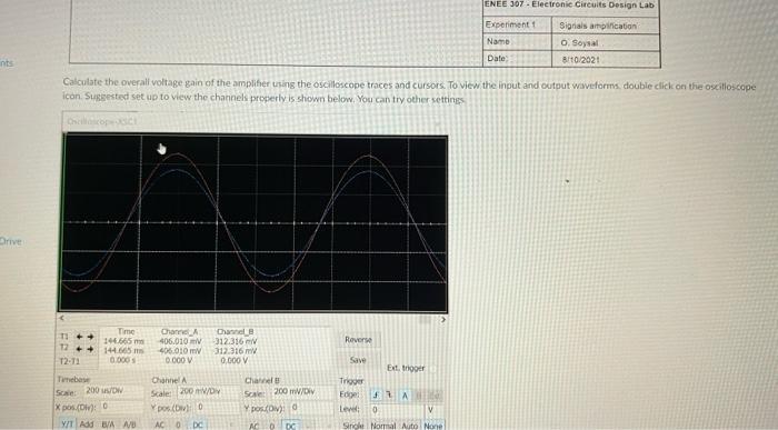

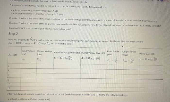
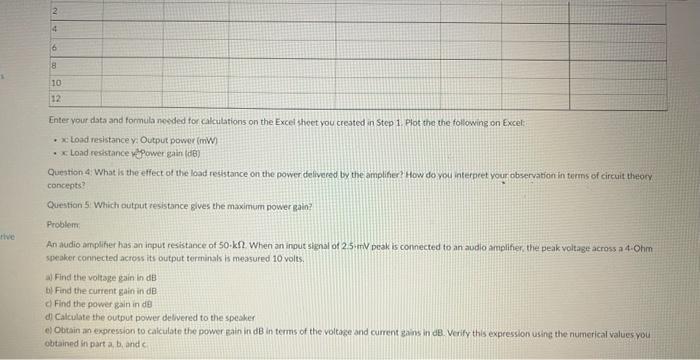
The "Aux" output of an audio device such as a CD player or tape recorder is specified by 500-mV peak voltage and 60-Ohm internal resistance. The figure below shows the Multisim schematic of the Thevenin equivalent circuit of this audio source. The voltage source may be arbitrarily set to 1 kHz sinusoidal waveform for simulation Signal Source R Vs (t) www 0.5Vpk 1kHz 0 This signal is amplified using an audio amplifier which has input resistance R, and output resistance Reut and 20 V/V voltage gain. This amplifier can be represented by the equivalent circuit below. Experiment 1 Procedure The "Aux" output of an audio device such as a CD player or tape recorder is specified by 500-mV peak voltage and 60-Ohm internal resistance. The figure below shows the Multisim schematic of the Thevenin equivalent circuit of this audio source. The voltage source may be arbitrarily set to 1-kHz, sinusoidal waveform for simulation. Signal Source R, ww 0.5Vpk 1kHz 0 This signal is amplified using an audio amplifier which has input resistance R... and output resistance R and 20 V/V voltage gain. This amplifier can be represented by the equivalent circuit below. This signal is amplified using an audio amplifier which has input resistance R. and output resistance Red and 20 V/V voltage gain. This amplifier can be represented by the equivalent circuit below. ww Rin Amplifier 1 + Rout 20V/V Your goal in this experiment is to determine the best values of input and output resistances of the amplifier for better performance. Step 1 First obtain the best input and output resistance values to obtain maximum voltage gain Start Multisen and build the schematic as shown below (The graphics and text on this diagram are only for information, you don't need to include rectangles and tw in your schematic). For beginning select the amplifier input and output resistances 10-Ohm (R.R-10 f nts Drive Step 1 First obtain the best input and output resistance values to obtain maximum voltage gain, Start Multisim and build the schematic as shown below (The graphics and text on this diagram are only for information, you don't need to include rectangles and text in your schematic). For beginning select the amplifier input and output resistances 10-Ohm (R... R10 5 the The load is a standard speaker represented by a 4-Ohm resistor. Channel A is connected to the input of the amplifier and channel B is connected to the output. Note that different line colors are selected for each channel. When you run the simulation the oscilloscope traces will match the line colors and it will be easier to distinguish the input and output signals. To change the line color, right click on the line and choose the "Segment Color" option Signal Source R m v. (t) (2 0.5Vpk 1kHz 0 Rin Amplifier Rest ww 20V/V Load (speaker) RL ENEE 307-Electronic Circuits Design Lab Experiment 1 Signais amplification) ints Drives Calculate the overall voltage gain of the amplifier using the oscilloscope traces and cursors. To view the input and output waveforms, double click on the oscilloscope icon. Suggested set up to view the channels properly is shown below. You can try other settings Oscilloscope C 12 12-71 Time 144.665 mm 144.665 0.000 Timebase Scale: 200 uu/DW Xpos.(DW): 0 YIT Add B/A A/D Channe A 406.010 V 406.010 mW 0.000 V Channel B 312.316 V 312.316 mv 0,000 V Channel A Scale: 200 mV/Div pos (D) D AC 0 DC Channel B Scale: 200 mV/DV Y pos(Div): 0 AC 0 DC Reverse Save Trigger Edge: Level: 0 Ext, trigger FRA ENEE 307- Electronic Circuits Design Lab Signials amplification Experiment 1 Name Date: O. Soysal 8/10/2021 14 V Single Normal Auto None ments neDrive Fill the table below by using the oscilloscope one of the cursors (the vertical line on the left side of oscilloscope screen to the peak value of the output signal and note down the values, You may need to change oscilloscope settings to see the traces better and take more accurate measurements. Rin (1) Rt (2) V) Vin 10 100 1.000 10 10 10 10,000 10 100,000 10 100,000 8 100,000 6 14 2 100,000 100.000 Input Voltage Output Amplifier Voltage Gain Voltage (V) for RL-00 (dB) Vent 20 logo G S Overall Voltage Gain XdB) A-20 log it is more convenient to create this table on Excel and do the calculations directly Enter your data and formula needed for calculations on an Excel sheet. Plot the the following on Excel Input resistance y: Overall voltage gain A (dB) Output resistance y Amplifier voltage gain G (dB) Input Power Output Power mw (mW) Pa P ya Power Gain (dB) P=10 log Question 1: What is the effect of the input resistance on the overall voltage gain? How do you interpret your observation in terms of circuit theory concepts Question 2: What is the effect of the output resistance on the amplifier voltage ain? How do you internet veur Question 1: What is the effect of the input resistance on the overall voltage gain? How do you interpret your observation in terms of circuit theory concepts? Question 2: What is the effect of the output resistance on the amplifier voltage gain? How do you interpret your observation in terms of circuit theory concepts? Question 3: Which set of values give the maximum voltage gain? Step 2 Now you are going to find the load resistance that can absorb maximum power from the amplifier output. Set the amplifier input resistance to R100 kft, Rout= 42. Change R, and fill the table below. it is more convenient to create this table on Excel and do the calculations directly Enter your data and formula needed for calculations on an Excel sheet. Plot the the following on Excel: R (2) 2 4 6 8 x Input resistance y: Overall voltage gain A (dB) x Output resistance y: Amplifier voltage gain G (dB) 10 12 Input Voltage Output Voltage Amplifier Voltage Gain (dB) Overall Voltage Gain (dB) ImV) (mv) G=20logi A-20 log Vin Vout Input Power (mW) Output Power mW) P... =/ P Enter your data and formula needed for calculations on the Excel sheet you created in Step 1. Plot the the following on Excel .x Load resistance y: Output power (mW) Power Gain (dB) P-10 log rive 2 4 (6 8 10 12 Enter your data and formula needed for calculations on the Excel sheet you created in Step 1. Plot the the following on Excel: .x Load resistance y: Output power (W) x Load resistance Power gain (dB) Question 4: What is the effect of the load resistance on the power delivered by the amplifier? How do you interpret your observation in terms of circuit theory concepts? Question 5: Which output resistance gives the maximum power gain? Problem An audio amplifier has an input resistance of 50-kft. When an input signal of 2.5mV peak is connected to an audio amplifier, the peak voltage across a 4-Ohm speaker connected across its output terminals is measured 10 volts. a) Find the voltage gain in dB b) Find the current gain in dB c) Find the power gain in dB d) Calculate the output power delivered to the speaker e) Obtain an expression to calculate the power gain in dB in terms of the voltage and current gains in dB. Verify this expression using the numerical values you obtained in part a, b, and c
Step by Step Solution
3.54 Rating (157 Votes )
There are 3 Steps involved in it

Get step-by-step solutions from verified subject matter experts