

Question: Please draw a schematic with clear inputs and outputs that accomplishes the task below. **Basic logic gates should not be used. Only use high level
Please draw a schematic with clear inputs and outputs that accomplishes the task below. **Basic logic gates should not be used. Only use high level components such as MUX's
Task: Create an instruction decoder which takes [3:0] opcode as an input and outputs capture_C, capture_Z, and capture_N. Use components such as MUX's and decoders, registers, etc (whatever is needed). However, there can be no other inputs or outputs added to the design.
The goal is to design a piece of hardware that accepts a four-bit opcode input, and produces the appropriate values of capture_C, capture_Z, and capture_N according to the table below.
The truth table for the decoder is below, in case it helps.
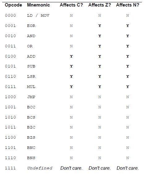
Opcode Mnemonic Affects C? Affects Z? Affects N? 0000 LD / MOV N N N 0001 EOR N Y Y 0010 AND N Y 0011 OR N Y Y 0100 ADD Y Y Y 0101 SUB Y Y Y 0110 LSR Y Y Y 0111 MUL Y Y Y 1000 JMP N N N . 1001 N N N 1010 BCS N N N 1011 BZC N N N 1100 BZS N N N 1101 BNC N N N 1110 BNS N N N 1111 Undefined Don't care. Don't care. Don't care
Step by Step Solution
There are 3 Steps involved in it

Get step-by-step solutions from verified subject matter experts