

Question: Please Explain Clearly. Design a network as shown below in Figure 1, and perform a performance test for each set of applications as shown in
Please Explain Clearly.
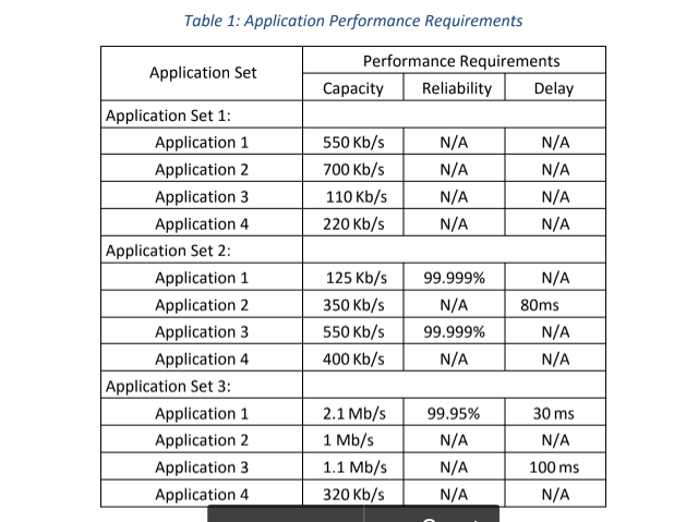
Design a network as shown below in Figure 1, and perform a performance test for each set of applications as shown in following Table 1 to validate them. For the network design in Figure 1, Application Sets 1, 2, 3 and 4 in table 1, are located in LAN A, B, C and D respectively.
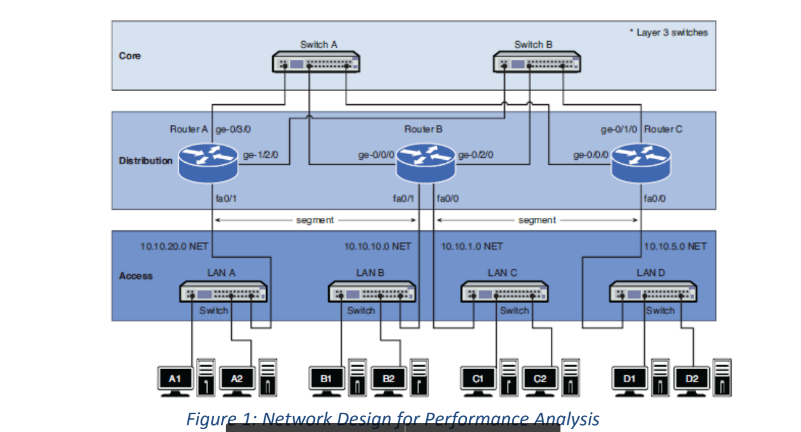
Layer 3 switches Switch A Switch B Core Router A ge-030 Router B ge-0/1/0 Router 9e-1/20 ge-000 Distrbution fa0/1 fa00 0.10.20.0 NET 10.10.10.0 NET 0.10.1.0 NET 0.10.5.0 NET LAN A LAN B LAN C LAN D Switch witch A1 A2 C1 C2 D1 D2 Figur lysis Layer 3 switches Switch A Switch B Core Router A ge-030 Router B ge-0/1/0 Router 9e-1/20 ge-000 Distrbution fa0/1 fa00 0.10.20.0 NET 10.10.10.0 NET 0.10.1.0 NET 0.10.5.0 NET LAN A LAN B LAN C LAN D Switch witch A1 A2 C1 C2 D1 D2 Figur lysis
Step by Step Solution
There are 3 Steps involved in it

Get step-by-step solutions from verified subject matter experts