

Question: Please finish the verilog coding and simulation for (a) and (b) 2. The functional unit UART Clock Generator in Figure P7-2 can be used to
Please finish the verilog coding and simulation for (a) and (b)
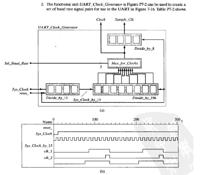
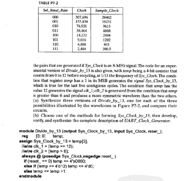
2. The functional unit UART Clock Generator in Figure P7-2 can be used to create a set of baud rate signal pairs for use in the UART in Figure 7-16. Table P7-2 shows Clock Sample Ck UART_Clock Generator Divide by8 Sel_Baud Raie Muxor_C locks Sys_Clock reset Divide by_13 Sys Clock by_13 Divide_by 256 100 200 300 Name reset Sys Clock Sys Clock by 13 clk 1 cik 2 2. The functional unit UART Clock Generator in Figure P7-2 can be used to create a set of baud rate signal pairs for use in the UART in Figure 7-16. Table P7-2 shows Clock Sample Ck UART_Clock Generator Divide by8 Sel_Baud Raie Muxor_C locks Sys_Clock reset Divide by_13 Sys Clock by_13 Divide_by 256 100 200 300 Name reset Sys Clock Sys Clock by 13 clk 1 cik 2
Step by Step Solution
There are 3 Steps involved in it

Get step-by-step solutions from verified subject matter experts