

Question: please give me the Boolean equations for the Controller Sections above. thanks For this assignment, you are allowed to use any built-in circuit elements of
 please give me the Boolean equations for the Controller Sections above. thanks
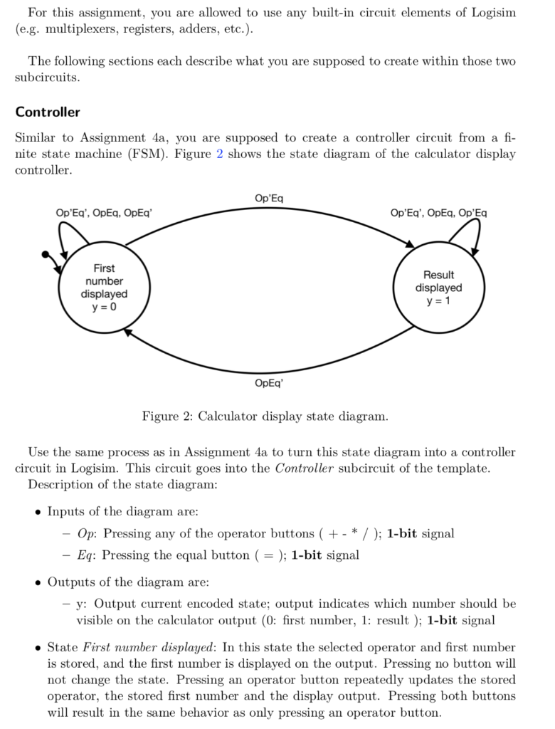
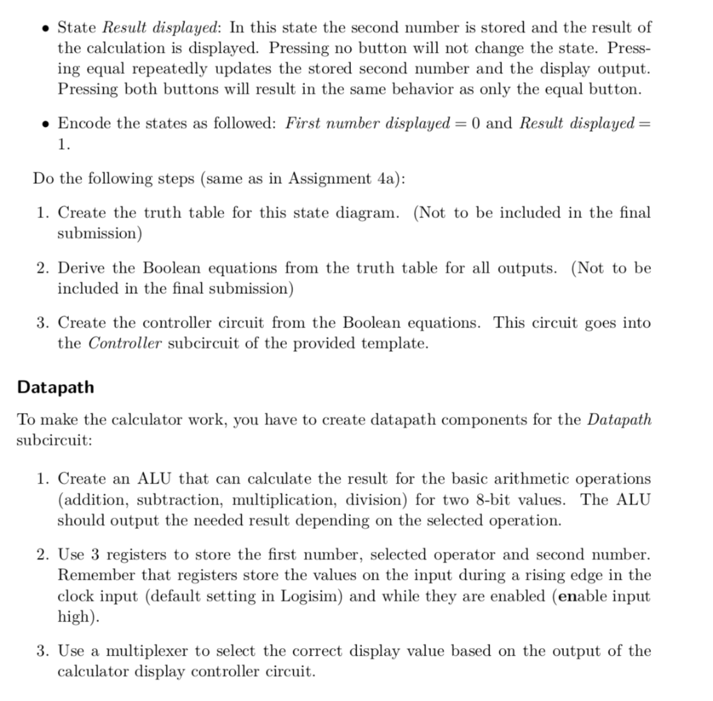
For this assignment, you are allowed to use any built-in circuit elements of Logisim (e.g. multiplexers, registers, adders, etc.) The following sections each describe what you are supposed to create within those two subcircuits Controller Similar to Assignment 4a, you are supposed to create a controller circuit from a fi- nite state machine (FSM). Figure 2 shows the state diagram of the calculator display controller Op'Eq Op'Eq', OpEq, OpEq' First number displayed Result displayed OpEq' Figure 2: Calculator display state diagram Use the same process as in Assignment 4a to turn this state diagram into a controller circuit in Logisim. This circuit goes into the Controller subcircuit of the template Description of the state diagram Inputs of the diagram are Op: Pressing any of the operator buttons (+ - * /); 1-bit signal Eq: Pressing the equal button ( = ); 1-bit signal . Outputs of the diagram are y: Output current encoded state; output indicates which number should be visible on the calculator output (0: first number, 1: result); 1-bit signal . State First number displayed: In this state the selected operator and first number is stored, and the first number is displayed on the output. Pressing no button will not change the state. Pressing an operator button repeatedly updates the stored operator, the stored first number and the display output. Pressing both buttons will result in the same behavior as only pressing an operator button . State Result displayed: In this state the second number is stored and the result of the calculation is displayed. Pressing no button will not change the state. Press- ing equal repeatedly updates the stored second number and the display output. Pressing both buttons will result in the same behavior as only the equal button. Encode the states as followed: First number displayed-0 and Result displayed - 1. Do the following steps (same as in Assignment 4a): 1. Create the truth table for this state diagram. (Not to be included in the final submission) included in the final submission) the Controller subcircuit of the provided template. 2. Derive the Boolean equations from the truth table for all outputs. (Not to be 3. Create the controller circuit from the Boolean equations. This circuit goes into Datapath To make the calculator work, you have to create datapath components for the Datapath subcircuit: 1. Create an ALU that can calculate the result for the basic arithmetic operations (addition, subtraction, multiplication, division) for two 8-bit values. The ALU should output the needed result depending on the selected operation. 2. Use 3 registers to store the first number, selected operator and second number. Remember that registers store the values on the input during a rising edge in the clock input (default setting in Logisim) and while they are enabled (enable input high). 3. Use a multiplexer to select the correct display value based on the output of the calculator display controller circuit
Step by Step Solution
There are 3 Steps involved in it

Get step-by-step solutions from verified subject matter experts