

Question: Please give the answer in the figure 5 attached below. 3. The diagram of a master-slave latch is shown in Fig. 2 below. Given a
Please give the answer in the figure 5 attached below.
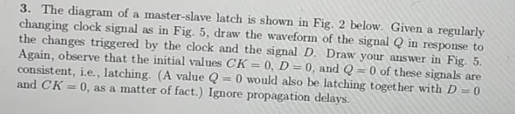
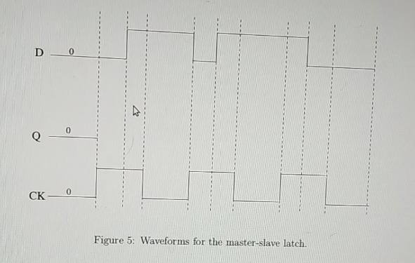
3. The diagram of a master-slave latch is shown in Fig. 2 below. Given a regularly changing clock signal as in Fig. 5, draw the waveform of the signal Q in response to the changes triggered by the clock and the signal D. Draw your answer in Fig. 5 Again, observe that the initial values CK = 0, D = 0, and Q-0 of these signals are consistent, i.e., latching. (A value Q-0 would also be latching together with D 0 and CK 0, as a matter of fact.) Ignore propagation delays. CK Figure 2:. The master-slave latch. 0 CK0 Figure 5: Waveforms for the master-slave latch
Step by Step Solution
There are 3 Steps involved in it
1 Expert Approved Answer
Step: 1 Unlock

Question Has Been Solved by an Expert!
Get step-by-step solutions from verified subject matter experts
Step: 2 Unlock
Step: 3 Unlock