

Question: Please note that the question and answer differs from any posted before on Chegg, please don't copy they are different. I will upvote! Answer each
-
Please note that the question and answer differs from any posted before on Chegg, please don't copy they are different. I will upvote!
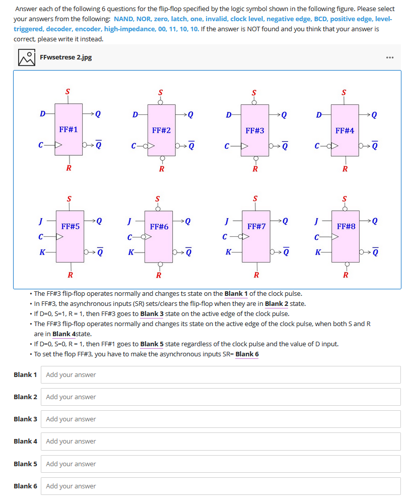
Answer each of the following 6 questions for the flip-flop specified by the logic symbol shown in the following figure. Please select your answers from the following: NAND, NOR, zero, latch, one, invalid, clock level, negative edge, BCD, positive edge, level- triggered, decoder, encoder, high-impedance, 00, 11, 10, 10. If the answer is NOT found and you think that your answer is correct, please write it instead. hi FFWsetrese 2.jpg S S D Q D Q D Q D Q FF#1 FF#2 FF#3 FF#4 CD b C- b CD 6-> C- b R R R R S J Q J Q Q Q FF#5 FF#6 FF#7 FF#8 C C C C K b K be K b K 0 R R R R The FF#3 flip-flop operates normally and changes ts state on the Blank 1 of the clock pulse. In FF#3, the asynchronous inputs (SR) sets/clears the flip-flop when they are in Blank 2 state. If D=0, S=1, R = 1, then FF#3 goes to Blank 3 state on the active edge of the clock pulse. The FF#3 flip-flop operates normally and changes its state on the active edge of the clock pulse, when both S and R are in Blank 4state. If D=0, S=O, R = 1, then FF#1 goes to Blank 5 state regardless of the clock pulse and the value of D input. To set the flop FF#3, you have to make the asynchronous inputs SR= Blank 6 Blank 1 Add your answer Blank 2 Add your answer Blank 3 Add your answer Blank 4 Add your answer Blank 5 Add your answer Blank 6 Add your
Step by Step Solution
There are 3 Steps involved in it

Get step-by-step solutions from verified subject matter experts