

Question: please provide the full actual circuit using gates and not block notation, thanks you can draw by hand or online either way works Adder/Subtractor Using
please provide the full actual circuit using gates and not block notation, thanks 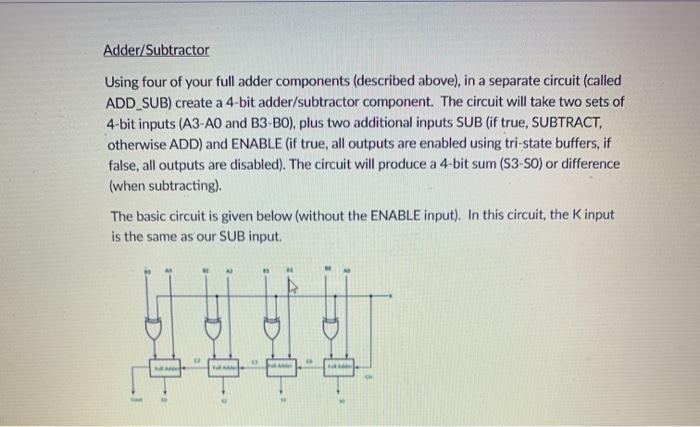
you can draw by hand or online either way works
Adder/Subtractor Using four of your full adder components (described above), in a separate circuit (called ADD_SUB) create a 4-bit adder/subtractor component. The circuit will take two sets of 4-bit inputs (A3-AO and B3-BO), plus two additional inputs SUB (if true, SUBTRACT, otherwise ADD) and ENABLE (if true, all outputs are enabled using tri-state buffers, if false, all outputs are disabled). The circuit will produce a 4-bit sum (S3-SO) or difference (when subtracting). The basic circuit is given below (without the ENABLE input). In this circuit, the Kinput is the same as our SUB input
Step by Step Solution
There are 3 Steps involved in it
1 Expert Approved Answer
Step: 1 Unlock

Question Has Been Solved by an Expert!
Get step-by-step solutions from verified subject matter experts
Step: 2 Unlock
Step: 3 Unlock