

Question: please solve all the questions EXAMPLE QUESTION Figure below shows two tanks in series fed with pure water. Water is continuously fed to the first
please solve all the questions
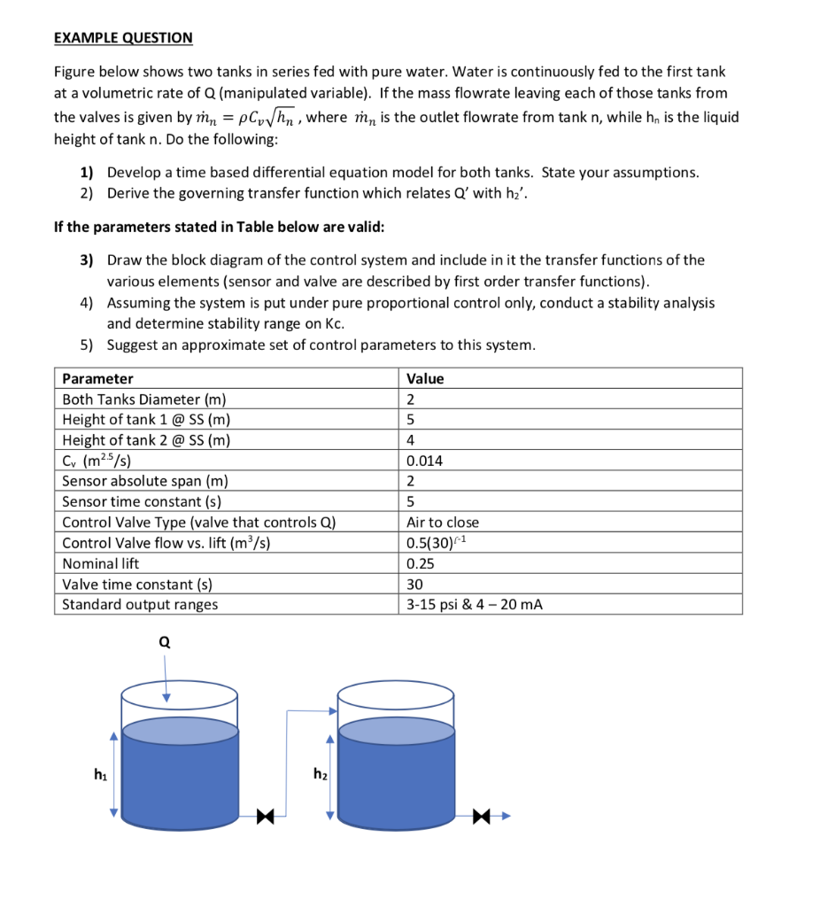
EXAMPLE QUESTION Figure below shows two tanks in series fed with pure water. Water is continuously fed to the first tank at a volumetric rate of Q (manipulated variable). If the mass flowrate leaving each of those tanks from the valves is given by n = pCohn, where my is the outlet flowrate from tank n, while h, is the liquid height of tank n. Do the following: 1) Develop a time based differential equation model for both tanks. State your assumptions. 2) Derive the governing transfer function which relates Q' with h2'. If the parameters stated in Table below are valid: 3) Draw the block diagram of the control system and include in it the transfer functions of the various elements (sensor and valve are described by first order transfer functions). 4) Assuming the system is put under pure proportional control only, conduct a stability analysis and determine stability range on Kc. 5) Suggest an approximate set of control parameters to this system. Value 2 5 4 Parameter Both Tanks Diameter (m) Height of tank 1 @ SS (m) Height of tank 2 @ SS (m) Cv (m25/s) Sensor absolute span (m) Sensor time constant (s) Control Valve Type (valve that controls Q) Control Valve flow vs. lift (m/s) Nominal lift Valve time constant (s) Standard output ranges 0.014 2 5 Air to close 0.5(30)(1 0.25 30 3-15 psi & 4-20 mA Q hi EXAMPLE QUESTION Figure below shows two tanks in series fed with pure water. Water is continuously fed to the first tank at a volumetric rate of Q (manipulated variable). If the mass flowrate leaving each of those tanks from the valves is given by n = pCohn, where my is the outlet flowrate from tank n, while h, is the liquid height of tank n. Do the following: 1) Develop a time based differential equation model for both tanks. State your assumptions. 2) Derive the governing transfer function which relates Q' with h2'. If the parameters stated in Table below are valid: 3) Draw the block diagram of the control system and include in it the transfer functions of the various elements (sensor and valve are described by first order transfer functions). 4) Assuming the system is put under pure proportional control only, conduct a stability analysis and determine stability range on Kc. 5) Suggest an approximate set of control parameters to this system. Value 2 5 4 Parameter Both Tanks Diameter (m) Height of tank 1 @ SS (m) Height of tank 2 @ SS (m) Cv (m25/s) Sensor absolute span (m) Sensor time constant (s) Control Valve Type (valve that controls Q) Control Valve flow vs. lift (m/s) Nominal lift Valve time constant (s) Standard output ranges 0.014 2 5 Air to close 0.5(30)(1 0.25 30 3-15 psi & 4-20 mA Q hi
Step by Step Solution
There are 3 Steps involved in it

Get step-by-step solutions from verified subject matter experts