

Question: Please use only one OUTPUT for each light. Use counters and timers. Use counter, greater than, normally open and closed push buttons. Nothing too advanced
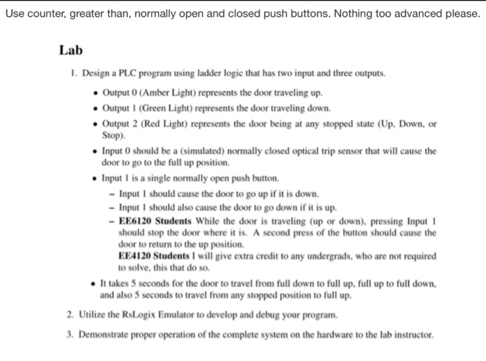
Use counter, greater than, normally open and closed push buttons. Nothing too advanced please. Lab 1. Design a PLC program using ladder logic that has two input and three outputs Output O (Amber Light) represents the door traveling up. Output 1 (Green Light) represents the door traveling down. Output 2 (Red Light) represents the door being at any stopped state (Up. Down, or Stop) Input 0 should be a (simulated) normally closed optical trip sensor that will cause the door to go to the full up position. Input 1 is a single normally open push button Input 1 should cause the door to go up if it is down. Input 1 should also cause the door to go down if it is up. EE6120 Students While the door is traveling (up or down), pressing Input should stop the door where it is. A second press of the button should cause the door to return to the up position. EE4120 Students I will give extra credit to any undergrads, who are not required to solve, this that do so. It takes 5 seconds for the door to travel from full down to full up, full up to full down, and also 5 seconds to travel from any stopped position to full up. 2. Utilize the RsLogix Emulator to develop and debug your program 3. Demonstrate proper operation of the complete system on the hardware to the lab instructor
Step by Step Solution
There are 3 Steps involved in it

Get step-by-step solutions from verified subject matter experts