

Question: Please write using ARM Assembly for STM 3 2 F 4 1 1 VETx and an STM 3 2 Microcontroller . The modes interact with
Please write using ARM Assembly for STM F VETx and an STM Microcontroller The modes interact with the LEDs on the board, and should be subroutines. It should all be one block of code.
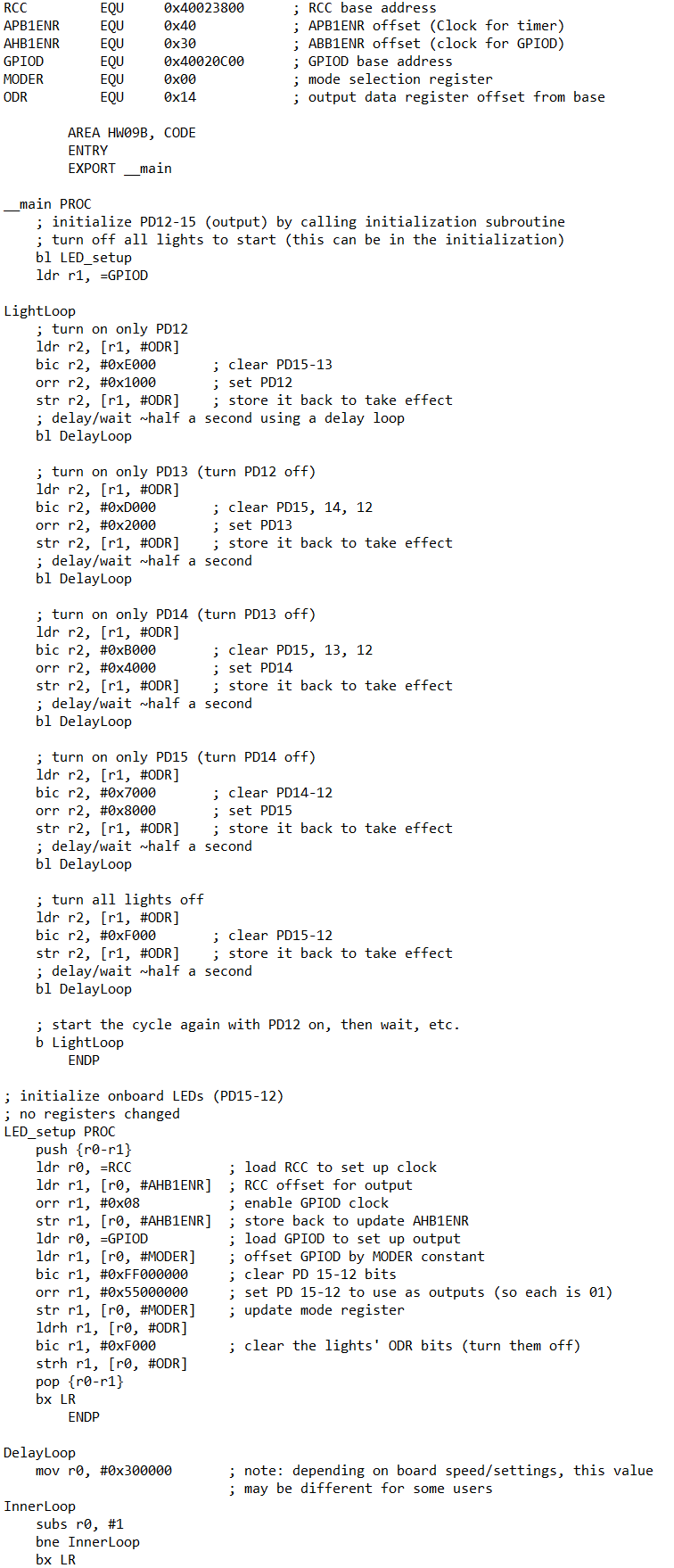
Please note the attached screenshot is an example of what our code has looked like in the past! While the function of the attached code will not help while answering this question, im hoping it should help you understand the snytax and formatting for this code.
The final project will entail writing a program with three modes: Mode A The lights will start all off, then turn on and stay on one at a time: orange, then red, then blue, and lastly green. They will then turn off and stay off one at a time in that same order. Once all are off, the cycle will repeat. Put a second pause between each change. For example, if all lights are off, the orange LED will come on and stay on then seconds later the red LED will also come on seconds after that, the blue LED will come on etc. Mode B The blue light will toggleblink once per second, the red light will toggle every seconds, the orange light will toggle every half second, and the green light will toggle every seconds. Mode C The program will read in byte values from a nullterminated, readonly array called ModeCVals and display them on the lights. If the value is between and the bits will correspond such that PD represents bit PD for bit PD for bit and PD for bit For example, if the value to be displayed is thats so PD would be off, PD and PD would be on and PD would be off. If the value in the array is larger than decimal fifteen xF do not turn on any of the lights for its representation. Each values LED representation should display for one second before changing directly to the next value. The nulltermination character counts as a value its zero After displaying the final x value, loop around to the beginning of the ModCVals array and start displaying the values from the beginning again. The user will switch between these modes by pressing the PA input button. The change in mode can occur at any point during the mode as opposed to finishing the cycle of blinks before starting the next. When the button is pressed while the program is on Mode C it should loop around and begin Mode A again. Hints: Use an interrupt for the input. Debounce your input. If a timer triggers every seconds, then something that occurs every third timer trigger will occur once every seconds. Moving bits through to bits through is a matter of shifting. Make DATA area values to be used as counters or to track what mode youre in
Please note I already have had this question answered on chegg, but the answer was incomplete, and did not match the formatting I provided. Here is the code I was given:
AREA RESET, DATA, READONLY
EXPORT ResetHandler
ResetHandler
LDR SPestack ; Set stack pointer
AREA HWOOB, CODE, READONLY
IMPORT SystemInit
IMPORT main
BL SystemInit
BL main
B
main PROC
BL LEDInit ; Initialize LEDs and GPIO
BL ButtonInit ; Initialize button for mode switching
MOV R # ; R will keep track of the current mode
ModeSelect:
LDR RR ; Load button press status into R
CMP R # ; Check if button was pressed
BEQ ChangeMode ; If yes, change mode
CMP R # ; Check which mode is active
BEQ ModeA
CMP R #
BEQ ModeB
CMP R #
BEQ ModeC
ChangeMode:
ADD R R # ; Increment mode
CMP R #
MOVLE R # ; If mode index is reset to Mode A
B ModeSelect
ModeA:
BL PerformModeA ; Execute Mode A operation
B ModeSelect
ModeB:
BL PerformModeB ; Execute Mode B operation
B ModeSelect
ModeC:
BL PerformModeC ; Execute Mode C operation
B ModeSelect
ENDP
LEDInit PROC
PUSH LR
LDR RRCCAHBENR ; RCC AHB peripheral clock enable register
LDR RR
ORR R R #x ; Enable GPIOD clock
STR RR
LDR RGPIODMODER ; GPIOD mode register
LDR RR
MOV R #x ; Set mode to output for PDPD
ORR R R R
STR RR
POP PC
ENDP
ButtonInit PROC
PUSH LR
; Configuration code for button initialization with debouncing
POP PC
ENDP
PerformModeA PROC
PUSH LR
; Insert logic for Mode A LED sequence operations
POP PC
ENDP
PerformModeB PROC
PUSH LR
; Insert logic for Mode B LED blinking at different rates
POPAREA HWB CODE
ENTRY
EXPORT main
Step by Step Solution
There are 3 Steps involved in it
1 Expert Approved Answer
Step: 1 Unlock

Question Has Been Solved by an Expert!
Get step-by-step solutions from verified subject matter experts
Step: 2 Unlock
Step: 3 Unlock