

Question: PLS HELP ME :( Even if you don't do it completely, it is very valuable to bring it up to a point.This is very important
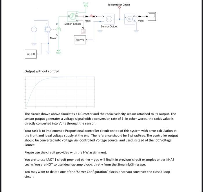
To controller Circuit rad/s Volts C Motion Sensor Sensor Output Motor f(x) = 0 f(x)=0 Output without control: The circuit shown above simulates a DC-motor and the radial velocity sensor attached to its output. The sensor putput generates a voltage signal with a conversion rate of 1. In other words, the rad/s value is directly converted into Volts through the sensor Your task is to implement a Proportional-controller circuit on top of this system with error calculation at the front and ideal voltage supply at the end. The reference should be 2.pi rad/sec. The controller output should be converted into voltage via 'Controlled Voltage Source' and used instead of the DC Voltage Source Please use the circuit provided with the HW assignment You are to use LM741 circuit provided earlier - you will find it in previous circuit examples under KHAS Learn. You are NOT to use ideal op-amp blocks diretly from the Simulink/Simscape. You may want to delete one of the 'Solver Configuration' blocks once you construct the closed-loop circuit. To controller Circuit rad/s Volts C Motion Sensor Sensor Output Motor f(x) = 0 f(x)=0 Output without control: The circuit shown above simulates a DC-motor and the radial velocity sensor attached to its output. The sensor putput generates a voltage signal with a conversion rate of 1. In other words, the rad/s value is directly converted into Volts through the sensor Your task is to implement a Proportional-controller circuit on top of this system with error calculation at the front and ideal voltage supply at the end. The reference should be 2.pi rad/sec. The controller output should be converted into voltage via 'Controlled Voltage Source' and used instead of the DC Voltage Source Please use the circuit provided with the HW assignment You are to use LM741 circuit provided earlier - you will find it in previous circuit examples under KHAS Learn. You are NOT to use ideal op-amp blocks diretly from the Simulink/Simscape. You may want to delete one of the 'Solver Configuration' blocks once you construct the closed-loop circuit
Step by Step Solution
There are 3 Steps involved in it

Get step-by-step solutions from verified subject matter experts