

Question: Prelab Part 2: Create schematic options for the circuit outputs Each of the three outputs of the 2bit adder will be generated by a 2:1
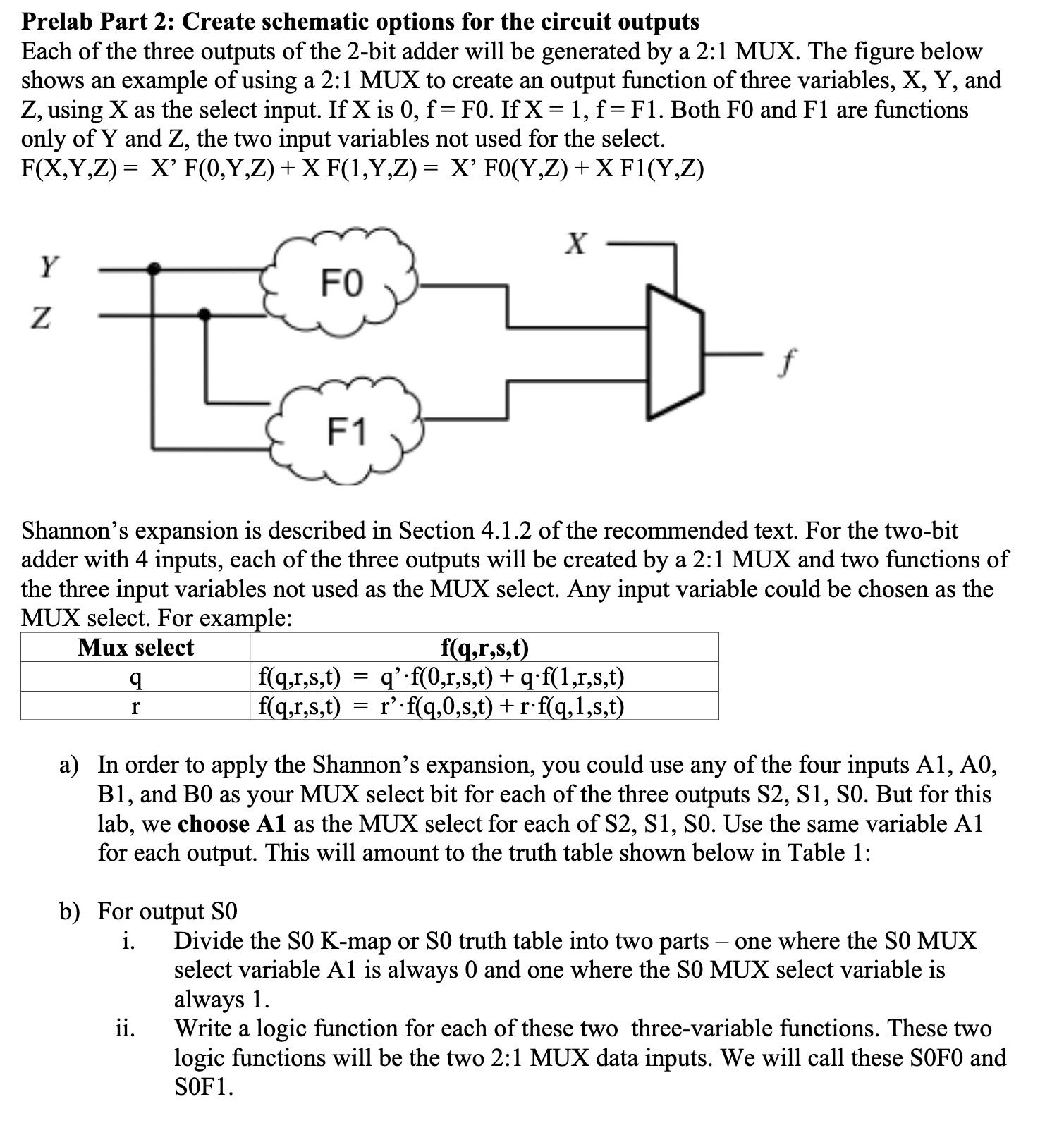
Prelab Part 2: Create schematic options for the circuit outputs Each of the three outputs of the 2bit adder will be generated by a 2:1 MUX. The gure below shows an example of using a 2:1 MUX to create an output function of three variables, X, Y, and Z, using X as the select input. If X is O, f = F0. If X = l, f = Fl. Both F0 and F l are functions only of Y and Z, the two input variables not used for the select. F(X,Y,Z) = X' F(0,Y,Z) + X F (1,Y,Z) = X' F0(Y,Z) + X F1(Y,Z) X Z - Shannon's expansion is described in Section 4.1.2 of the recommended text. For the two-bit adder with 4 inputs, each of the three outputs will be created by a 2:1 MUX and two functions of the three input variables not used as the MUX select. Any input variable could be chosen as the MUX select. For example: Mux select f(q,r,s,t) q f(q,r,s,t) = q'-f(0,r,s,t) + q-f(l,r,s,t) r f(q,r,s,t) = r'-f(g,0,s,t) +r-f(g,l,s,t) a) In order to apply the Shannon's expansion, you could use any of the four inputs Al, A0, B1, and B0 as your MUX select bit for each of the three outputs SZ, 81, SO. But for this lab, we choose A1 as the MUX select for each of S2, Sl, SO. Use the same variable Al for each output. This will amount to the truth table shown below in Table 1: b) For output SO i. Divide the SO K-map or SO truth table into two parts one where the SO MUX select variable Al is always 0 and one where the SO MUX select variable is always 1. ii. Write a logic function for each of these two three-variable mctions. These two logic functions will be the two 2:1 MUX data inputs. We will call these SOFO and SOFl
Step by Step Solution
There are 3 Steps involved in it

Get step-by-step solutions from verified subject matter experts