

Question: Problem 1 . Beam Analysis A simply supported 7 0 0 WB 1 5 0 beam ( bending about its strong axis ) is made
Problem Beam Analysis
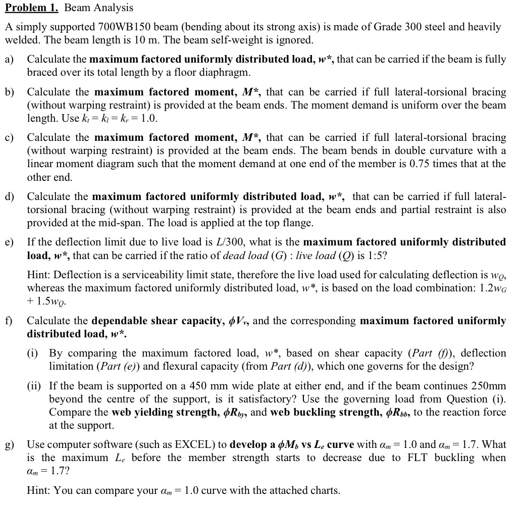
A simply supported WB beam bending about its strong axis is made of Grade steel and heavily welded. The beam length is m The beam selfweight is ignored.
a Calculate the maximum factored uniformly distributed load, that can be carried if the beam is fully braced over its total length by a floor diaphragm.
b Calculate the maximum factored moment, that can be carried if full lateraltorsional bracing without warping restraint is provided at the beam ends. The moment demand is uniform over the beam length. Use
c Calculate the maximum factored moment, that can be carried if full lateraltorsional bracing without warping restraint is provided at the beam ends. The beam bends in double curvature with a linear moment diagram such that the moment demand at one end of the member is times that at the other end.
d Calculate the maximum factored uniformly distributed load, that can be carried if full lateraltorsional bracing without warping restraint is provided at the beam ends and partial restraint is also provided at the midspan. The load is applied at the top flange.
e If the deflection limit due to live load is what is the maximum factored uniformly distributed load, that can be carried if the ratio of dead load : live load is :
Hint: Deflection is a serviceability limit state, therefore the live load used for calculating deflection is whereas the maximum factored uniformly distributed load, is based on the load combination:
f Calculate the dependable shear capacity, and the corresponding maximum factored uniformly distributed load,
i By comparing the maximum factored load, based on shear capacity Part f deflection limitation Part e and flexural capacity from Part d which one governs for the design?
ii If the beam is supported on a mm wide plate at either end, and if the beam continues mm beyond the centre of the support, is it satisfactory? Use the governing load from Question i Compare the web yielding strength, and web buckling strength, to the reaction force at the support.
g Use computer software such as EXCEL to develop a vs curve with and What is the maximum before the member strength starts to decrease due to FLT buckling when
Hint: You can compare your curve with the attached charts.
Step by Step Solution
There are 3 Steps involved in it
1 Expert Approved Answer
Step: 1 Unlock

Question Has Been Solved by an Expert!
Get step-by-step solutions from verified subject matter experts
Step: 2 Unlock
Step: 3 Unlock