

Question: Problem 1 The structure shown in Fig. 1 . 1 is made with a steel bar that has a rectangular cross - section 5 cm
Problem
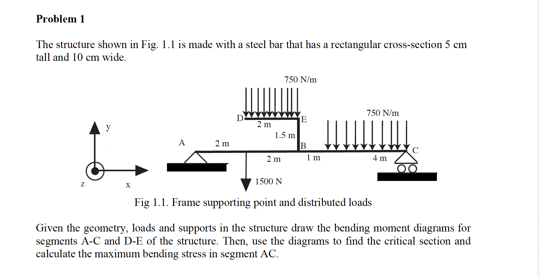
The structure shown in Fig. is made with a steel bar that has a rectangular crosssection cm
tall and cm wide.
Fig Frame supporting point and distributed loads
Given the geometry, loads and supports in the structure draw the bending moment diagrams for
segments AC and DE of the structure. Then, use the diagrams to find the critical section and
calculate the maximum bending stress in segment AC
Step by Step Solution
There are 3 Steps involved in it
1 Expert Approved Answer
Step: 1 Unlock

Question Has Been Solved by an Expert!
Get step-by-step solutions from verified subject matter experts
Step: 2 Unlock
Step: 3 Unlock