

Question: . Table 2 shows the state table for a Moore finite state machine that has two inputs x and y, one output z, and four
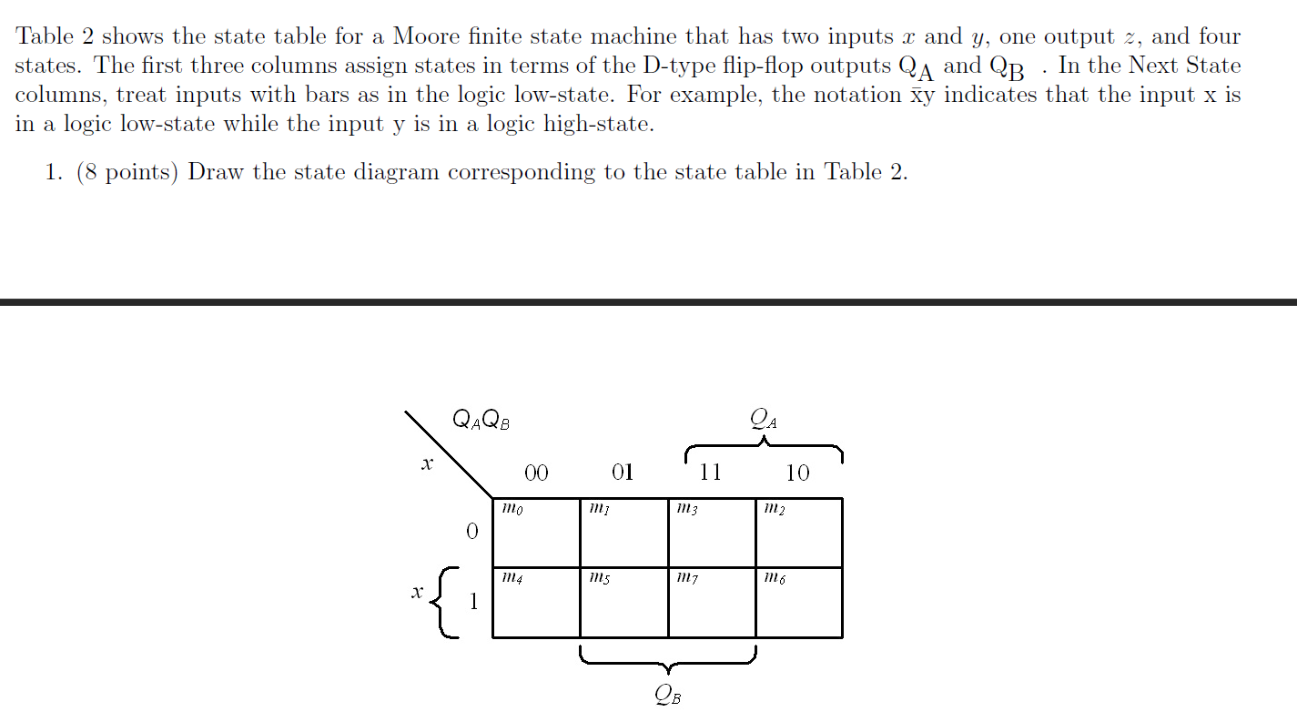
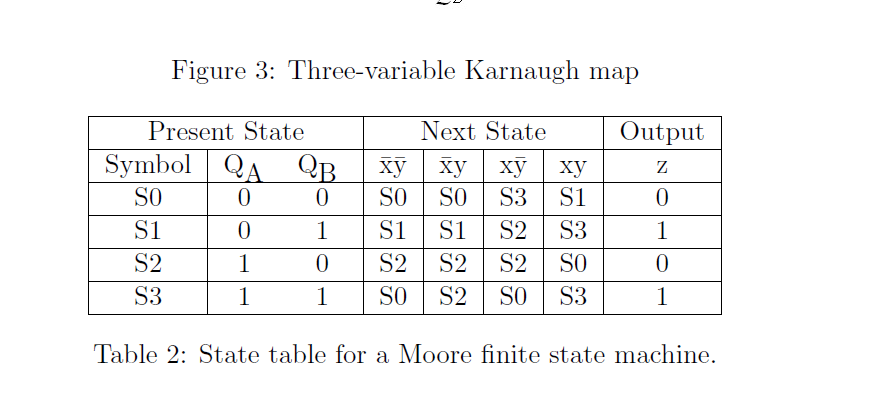

. Table 2 shows the state table for a Moore finite state machine that has two inputs x and y, one output z, and four states. The first three columns assign states in terms of the D-type flip-flop outputs QA and QB In the Next State columns, treat inputs with bars as in the logic low-state. For example, the notation ay indicates that the input x is in a logic low-state while the input y is in a logic high-state. 1. (8 points) Draw the state diagram corresponding to the state table in Table 2. QAQB x 00 01 11 10 mo m; m3 m2 0 M14 ms mz m16 X 1 QB 3 Figure 3: Three-variable Karnaugh map Output Z Present State Symbol QA QB SO 0 0 S1 0 1 S2 1 0 S3 1 1 Next State SO SO S3 S1 S1 S1 S2 S3 S2 S2 S2 SO SO S2 SO S3 0 1 0 0 1 Table 2: State table for a Moore finite state machine. 2. (10 points) Using the four-variable Karnaugh map in Figure 4, determine the excitation equations for the inputs DA and DB ; again, you will need a copy for each flip-flop input. To receive credit, mark all the minterms with either a 1 or 0 in the Karnaugh map. QAQB 00 01 11 10 mo mi 13 m2 00 01 m4 ms m17 mo m2 M13 m15 m14 11 X ms me m2 mio 10 QB Figure 4: Four-variable Karnaugh map 3. (10 points) Generate the signals DA and DB using only NAND gates with standard input counts. Assume the signals x, y, QA , and QB along with their complements are available. To receive credit, you must neatly sketch the logic circuit
Step by Step Solution
There are 3 Steps involved in it

Get step-by-step solutions from verified subject matter experts