

Question: Problem# 2 . Figure 2 shows the elevation of a moment frame along with a gravity - loadcarrying system. All beams and columns are oriented
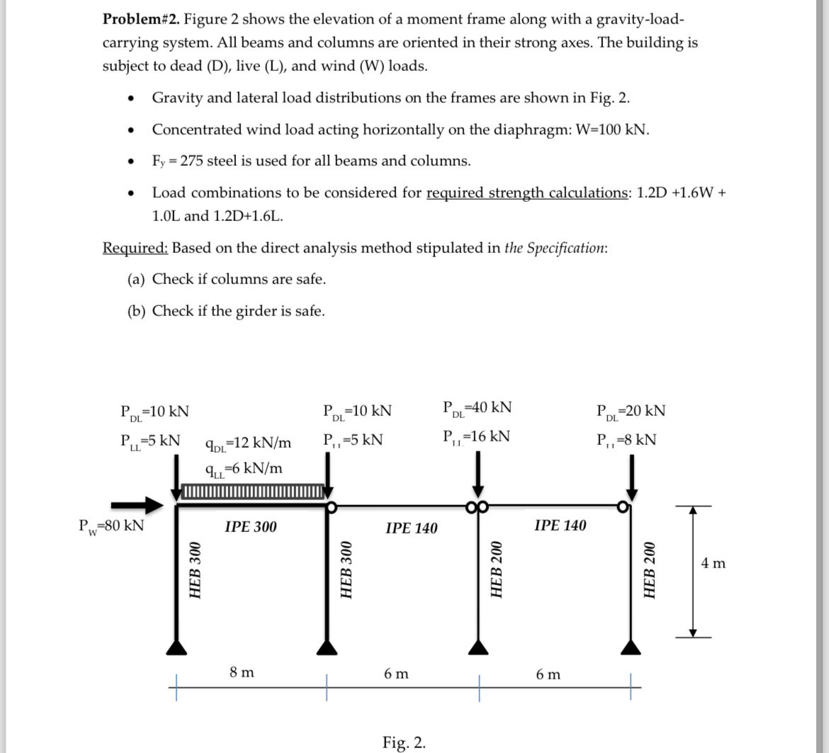
Problem# Figure shows the elevation of a moment frame along with a gravityloadcarrying system. All beams and columns are oriented in their strong axes. The building is subject to dead D live L and wind W loads.
Gravity and lateral load distributions on the frames are shown in Fig.
Concentrated wind load acting horizontally on the diaphragm:
steel is used for all beams and columns.
Load combinations to be considered for required strength calculations: and
Required: Based on the direct analysis method stipulated in the Specification:
a Check if columns are safe.
b Check if the girder is safe.
Fig.
Step by Step Solution
There are 3 Steps involved in it
1 Expert Approved Answer
Step: 1 Unlock

Question Has Been Solved by an Expert!
Get step-by-step solutions from verified subject matter experts
Step: 2 Unlock
Step: 3 Unlock