

Question: Problem 3 . 2 : SL S Design The beam shown in Figure 1 carries a uniformly distributed live load Q = 4 k N
Problem : SL S Design
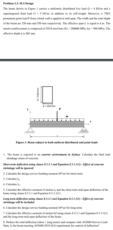
The beam shown in Figure carries a uniformly distributed live load and a superimposed dead load in addition to its selfweight. Moreover, a kN permanent point load P from a brick wall is applied at midspan. The width and the total depth of the beam are mm and mm respectively. The effective span is equal to m The tensile reinforcement is composed of N steel bars ; fsy MPa The effective depth d is mm
The beam is exposed to an exterior environment in Sydney. Calculate the final total shrinkage strain of concrete.
Short term deflection using clause and Equation I Effect of concrete shrinkage will be ignored:
Calculate the design service bending moment ser for shortterm.
Calculate
Calculate
Calculate the effective moment of inertia and the shortterm midspan deflection of the beam using clause and Equation
Long term deflection using clause and Equation I Effect of concrete shrinkage will be included.
Calculate the design service bending moment ser for longterm.
Calculate the effective moment of inertia lef using clause and Equation and the longterm midspan deflection of the beam.
Deduce the total deflection short long terms and compare with AS Service Limit State. Is the beam meeting AS SLS requirement for control of deflection?
Step by Step Solution
There are 3 Steps involved in it
1 Expert Approved Answer
Step: 1 Unlock

Question Has Been Solved by an Expert!
Get step-by-step solutions from verified subject matter experts
Step: 2 Unlock
Step: 3 Unlock