

Question: Problem 3: (30 points) Using D flip-flops, NAND gates and inverters available in your lab kit, design a Moore finite state machine with one input
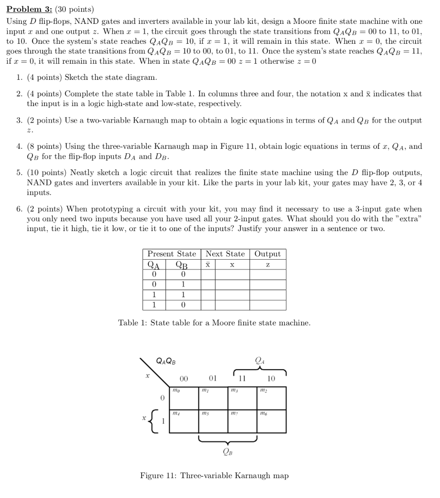
Problem 3: (30 points) Using D flip-flops, NAND gates and inverters available in your lab kit, design a Moore finite state machine with one input x and one output When x = 1, the circuit goes through the state transitions from QaQB = 00 to 11, to 01, to 10. Once the system's state reaches QAQB = 10, if x = 1, it will remain in this state. When z = 0, the circuit goes through the state transitions from QAQB = 10 to 00, to 01, to 11. Once the system's state reaches QaQB = 11 if 0, it will remain in this state. When in state QAQB 00 z1 otherwise z0 1. (4 points) Sketch the state diagram 2. (4 points) Complete the state table in Table 1. In columns three and four, the notation x and x indicates that 3. (2 points) Use a two-variable Karnaugh map to obtain a logic equations in terms of QA and QB for the output 4. (8 points) Using the three-variable Karnaugh map in Figure 11, obtain logic equations in terms of x, QA, and 5. (10 points) Neatly sketch a logic circuit that realizes the finite state machine using the D flip-flop outputs, the input is in a logic high-state and low-state, respectively QB for the flip-flop inputs DA and DB NAND gates and inverters available in your kit. Like the parts in your lab kit, your gates may have 2, 3, or 4 inputs 6. (2 points) When prototyping a circuit with your kit, you may find it necessary to use a 3-input gate when you only need two inputs because you have used all your 2-input gates. What should you do with the "extra" input, tie it high, tie it low, or tie it to one of the inputs? Justify your answer in a sentence or two Present State Next StateOutput 0 Table 1: State table for a Moore finite state machine 01 10 0 Figure 1: Three-variable Karnaugh map
Step by Step Solution
There are 3 Steps involved in it

Get step-by-step solutions from verified subject matter experts