

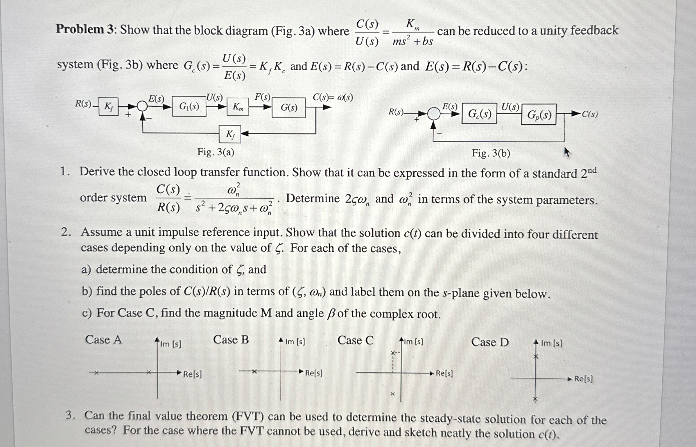
Question: Problem 3 : Show that the block diagram ( Fig . 3 a ) where C ( s ) U ( s ) = K
Problem : Show that the block diagram Figa where can be reduced to a unity feedback system Figb where and and :
Derive the closed loop transfer function. Show that it can be expressed in the form of a standard order system Determine and in terms of the system parameters.
Assume a unit impulse reference input. Show that the solution can be divided into four different cases depending only on the value of For each of the cases,
a determine the condition of and
b find the poles of in terms of and label them on the plane given below.
c For Case C find the magnitude M and angle of the complex root.
Can the final value theorem FVT can be used to determine the steadystate solution for each of the cases? For the case where the FVT cannot be used, derive and sketch neatly the solution
Step by Step Solution
There are 3 Steps involved in it
1 Expert Approved Answer
Step: 1 Unlock

Question Has Been Solved by an Expert!
Get step-by-step solutions from verified subject matter experts
Step: 2 Unlock
Step: 3 Unlock