

Question: Problem 3 . The block diagram of a control system is given in the figure: a ) Draw the block diagram in Laplace domain. b
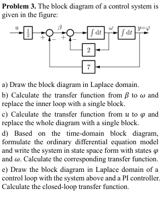
Problem The block diagram of a control system is given in the figure:
a Draw the block diagram in Laplace domain.
b Calculate the transfer function from beta to omega and replace the inner loop with a single block.
c Calculate the transfer function from u to varphi and replace the whole diagram with a single block.
d Based on the timedomain block diagram, formulate the ordinary differential equation model and write the system in state space form with states varphi and omega Calculate the corresponding transfer function.
e Draw the block diagram in Laplace domain of a control loop with the system above and a PI controller. Calculate the closedloop transfer function.
Step by Step Solution
There are 3 Steps involved in it
1 Expert Approved Answer
Step: 1 Unlock

Question Has Been Solved by an Expert!
Get step-by-step solutions from verified subject matter experts
Step: 2 Unlock
Step: 3 Unlock