

Question: Problem # 4 ( 1 0 0 points ) : The figure below shows a cantilevered bar of solid circular cross - section having
Problem # points:
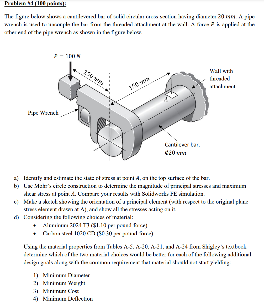
The figure below shows a cantilevered bar of solid circular crosssection having diameter mm A pipe wrench is used to uncouple the bar from the threaded attachment at the wall. A force P is applied at the other end of the pipe wrench as shown in the figure below.
a Identify and estimate the state of stress at point A on the top surface of the bar.
b Use Mohr's circle construction to determine the magnitude of principal stresses and maximum shear stress at point A Compare your results with Solidworks FE simulation.
c Make a sketch showing the orientation of a principal element with respect to the original plane stress element drawn at A and show all the stresses acting on it
d Considering the following choices of material:
Aluminum T$ per poundforce
Carbon steel mathrmCD$ per poundforce
Using the material properties from Tables A A A and A from Shigley's textbook determine which of the two material choices would be better for each of the following additional design goals along with the common requirement that material should not start yielding:
Minimum Diameter
Minimum Weight
Minimum Cost
Minimum Deflection
I need the final answers along the solutions,thanks!
Step by Step Solution
There are 3 Steps involved in it
1 Expert Approved Answer
Step: 1 Unlock

Question Has Been Solved by an Expert!
Get step-by-step solutions from verified subject matter experts
Step: 2 Unlock
Step: 3 Unlock