

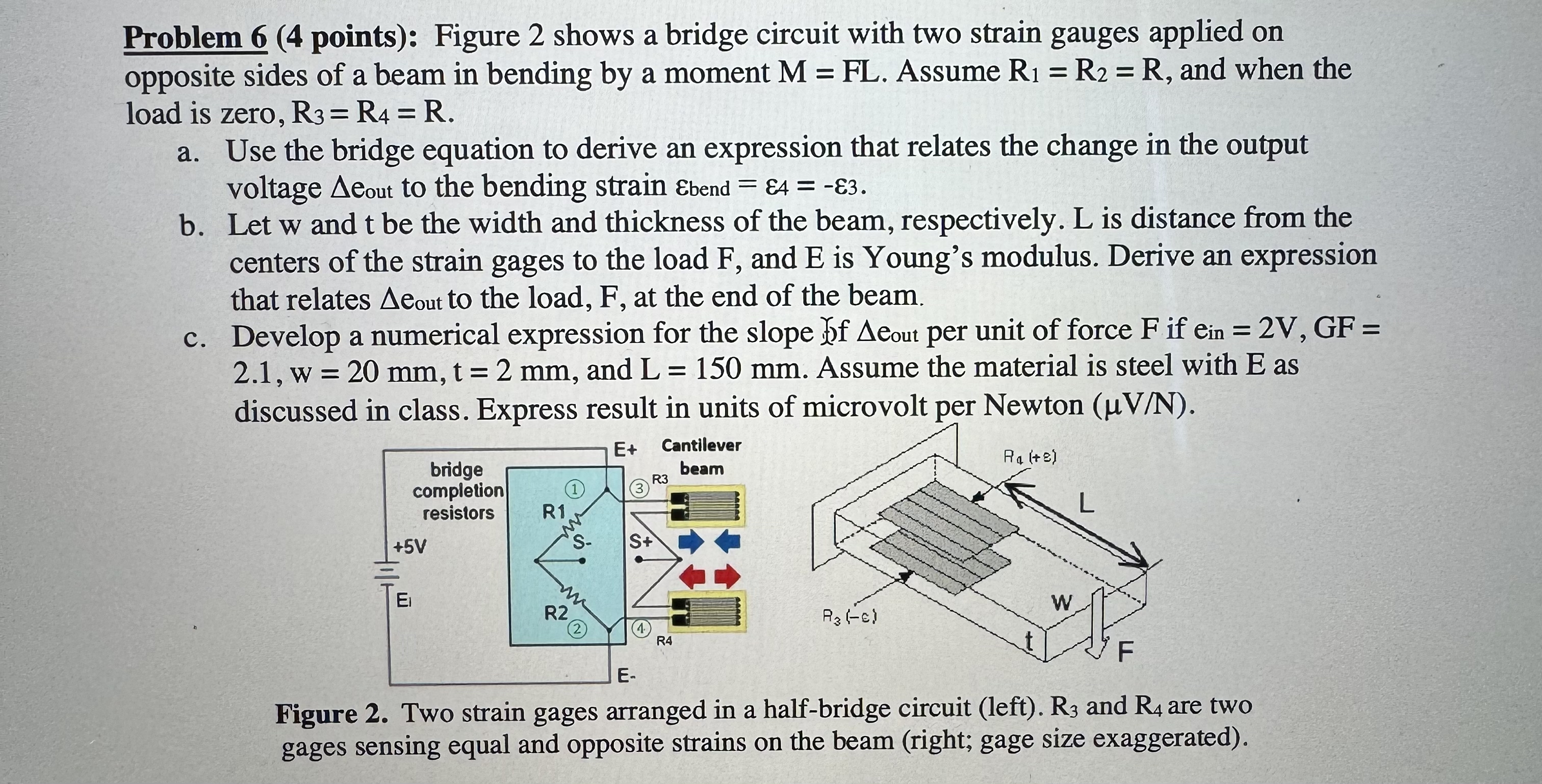
Question: Problem 6 ( 4 points ) : Figure 2 shows a bridge circuit with two strain gauges applied on opposite sides of a beam in
Problem points: Figure shows a bridge circuit with two strain gauges applied on opposite sides of a beam in bending by a moment Assume and when the load is zero,
a Use the bridge equation to derive an expression that relates the change in the output voltage to the bending strain
b Let and be the width and thickness of the beam, respectively. L is distance from the centers of the strain gages to the load F and E is Young's modulus. Derive an expression that relates to the load, F at the end of the beam.
c Develop a numerical expression for the slope per unit of force if and Assume the material is steel with E as discussed in class. Express result in units of microvolt per Newton
Figure Two strain gages arranged in a halfbridge circuit left and are two gages sensing equal and opposite strains on the beam right; gage size exaggerated
Step by Step Solution
There are 3 Steps involved in it
1 Expert Approved Answer
Step: 1 Unlock

Question Has Been Solved by an Expert!
Get step-by-step solutions from verified subject matter experts
Step: 2 Unlock
Step: 3 Unlock