

Question: Problem 6 : Active filters For the circuit topology ( a multi - feedback bandpass filter with voltage gain ) shown below, we claim that
Problem : Active filters
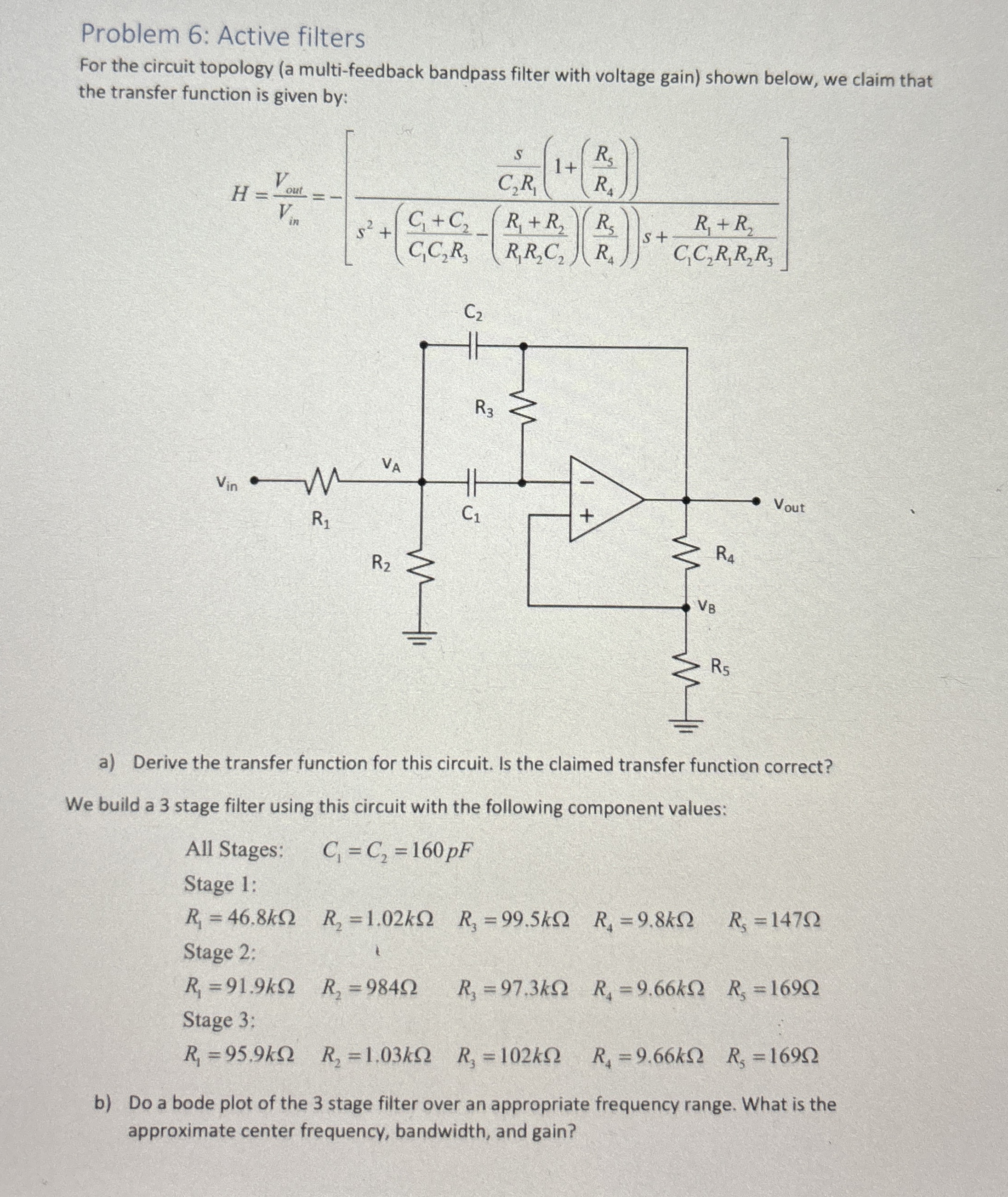
For the circuit topology a multifeedback bandpass filter with voltage gain shown below, we claim that the transfer function is given by:
a Derive the transfer function for this circuit. Is the claimed transfer function correct?
We build a stage filter using this circuit with the following component values:
All Stages:
Stage :
Stage :
Stage :
b Do a bode plot of the stage filter over an appropriate frequency range. What is the approximate center frequency, bandwidth, and gain?
Problem : Active filters
For the circuit topology a multifeedback bandpass filter with voltage gain shown below, we claim that the transfer function is given by:
a Derive the transfer function for this circuit. Is the claimed transfer function correct?
We build a stage filter using this circuit with the following component values:
All Stages:
Stage :
Stage :
Stage :
b Do a bode plot of the stage filter over an appropriate frequency range. What is the approximate center frequency, bandwidth, and gain?
Step by Step Solution
There are 3 Steps involved in it
1 Expert Approved Answer
Step: 1 Unlock

Question Has Been Solved by an Expert!
Get step-by-step solutions from verified subject matter experts
Step: 2 Unlock
Step: 3 Unlock