

Question: Problem: Given an antenna positioning system as shown below: The schematics of the system can be seen in the following figure: The values of the
Problem:
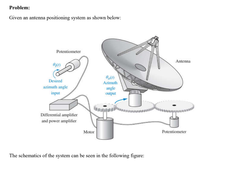
Given an antenna positioning system as shown below:
The schematics of the system can be seen in the following figure: The values of the parameters in the schematics can be seen below for configurations:
Schematic Parameters
Tasks:
Derive the mathematical models and block diagrams for configuration and
Simplify the block diagrams that you get in task until they become unity feedback systems
Design with reasonings PD controls on and with the following design requirements:
a Maximum overshoot b Settling time is seconds
cmathrmKmathrmvvelocity constant for steady state error with ramp input is
Show the simulation results of the PDcontrolled systems results of task in closedloop systems for configuration and and highlight the achievements compare with the simulation results of uncontrolledoriginal systems
Step by Step Solution
There are 3 Steps involved in it
1 Expert Approved Answer
Step: 1 Unlock

Question Has Been Solved by an Expert!
Get step-by-step solutions from verified subject matter experts
Step: 2 Unlock
Step: 3 Unlock