

Question: Problem Statement: Consider the pulley system shown, with shaft diameter d = 2 0 m m , pulley diameters d A = 2 5 0
Problem Statement:
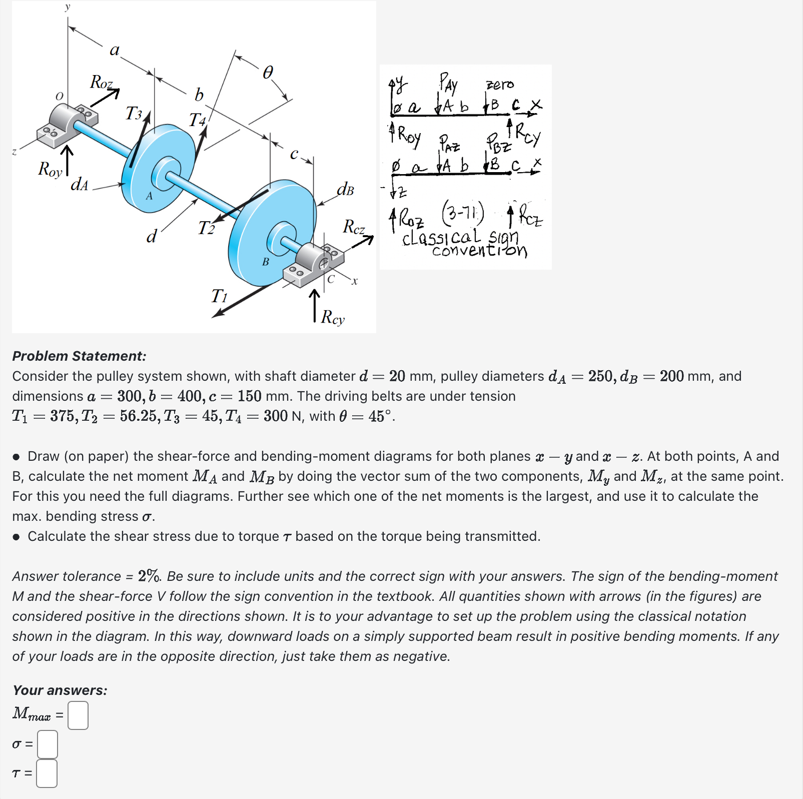
Consider the pulley system shown, with shaft diameter pulley diameters and
dimensions The driving belts are under tension
with
Draw on paper the shearforce and bendingmoment diagrams for both planes and At both points, A and
B calculate the net moment and by doing the vector sum of the two components, and at the same point.
For this you need the full diagrams. Further see which one of the net moments is the largest, and use it to calculate the
max. bending stress
Calculate the shear stress due to torque based on the torque being transmitted.
Answer tolerance Be sure to include units and the correct sign with your answers. The sign of the bendingmoment
and the shearforce follow the sign convention in the textbook. All quantities shown with arrows in the figures are
considered positive in the directions shown. It is to your advantage to set up the problem using the classical notation
shown in the diagram. In this way, downward loads on a simply supported beam result in positive bending moments. If any
of your loads are in the opposite direction, just take them as negative.
Your answers:
Step by Step Solution
There are 3 Steps involved in it
1 Expert Approved Answer
Step: 1 Unlock

Question Has Been Solved by an Expert!
Get step-by-step solutions from verified subject matter experts
Step: 2 Unlock
Step: 3 Unlock