

Question: Problem Statement: The cantilever beam shown in the figure is subjected to two - plane bending. It is loaded by P 1 = 4 8
Problem Statement:
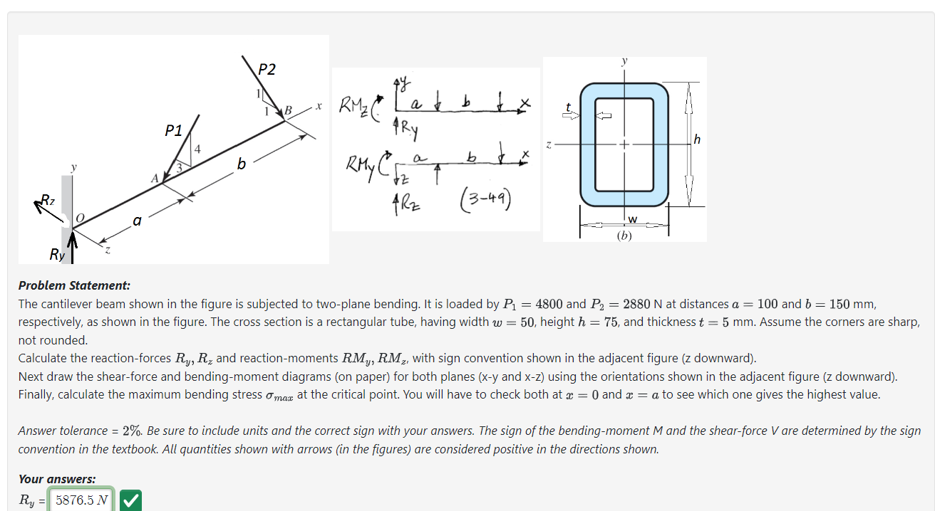
The cantilever beam shown in the figure is subjected to twoplane bending. It is loaded by and at distances and mm
respectively, as shown in the figure. The cross section is a rectangular tube, having width height and thickness mm Assume the corners are sharp,
not rounded.
Calculate the reactionforces and reactionmoments with sign convention shown in the adjacent figure z downward
Next draw the shearforce and bendingmoment diagrams on paper for both planes and using the orientations shown in the adjacent figure downward
Finally, calculate the maximum bending stress at the critical point. You will have to check both at and to see which one gives the highest value.
Answer tolerance Be sure to include units and the correct sign with your answers. The sign of the bendingmoment and the shearforce are determined by the sign
convention in the textbook. All quantities shown with arrows in the figures are considered positive in the directions shown.
Step by Step Solution
There are 3 Steps involved in it
1 Expert Approved Answer
Step: 1 Unlock

Question Has Been Solved by an Expert!
Get step-by-step solutions from verified subject matter experts
Step: 2 Unlock
Step: 3 Unlock