

Question: Process Engineering W1 R1 h A1 P1 W2 W The above process represents a buffer tank where w and w are input flow rates and
Process Engineering
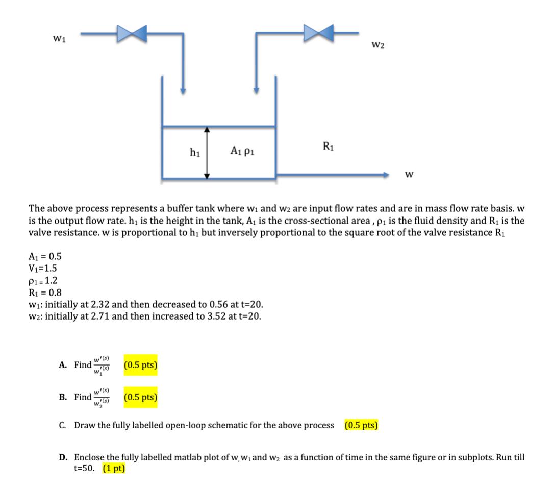
W1 R1 h A1 P1 W2 W The above process represents a buffer tank where w and w are input flow rates and are in mass flow rate basis. w is the output flow rate. h is the height in the tank, A is the cross-sectional area, p is the fluid density and R is the valve resistance. w is proportional to h but inversely proportional to the square root of the valve resistance R A = 0.5 V=1.5 P1 = 1.2 R = 0.8 W: initially at 2.32 and then decreased to 0.56 at t=20. W2: initially at 2.71 and then increased to 3.52 at t=20. w'(s) A. Find (0.5 pts) B. Find w'(s) w'(s) (0.5 pts) C. Draw the fully labelled open-loop schematic for the above process (0.5 pts) D. Enclose the fully labelled matlab plot of ww and w as a function of time in the same figure or in subplots. Run till t=50. (1 pt)
Step by Step Solution
There are 3 Steps involved in it

Get step-by-step solutions from verified subject matter experts