

Question: Project 4 : 4 - bit Processor make circuit diagram Design a 4 - bit processor which consists of 4 data registers each of 4
Project : bit Processor make circuit diagram
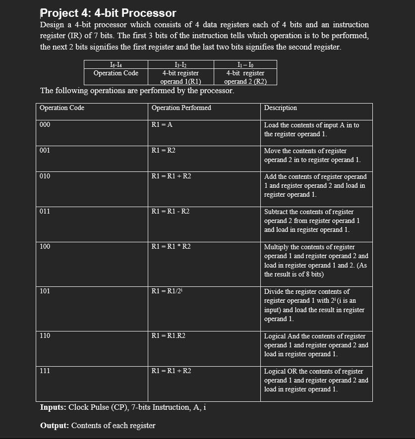
Design a bit processor which consists of data registers each of bits and an instruction register of bits. The first bits of the instruction tells which operation is to be performed, the next bits signifies the first register and the last two bits signifies the second register.
The following operations are performed by the processor.
R A Load the contents of input A in to the register operand
R R Move the contents of register operand in to register operand
R R R Add the contents of register operand and register operand and load in register operand
R R R Subtract the contents of register operand from register operand and load in register operand
R R R Multiply the contents of register operand and register operand and load in register operand and As the result is of bits
R Ri Divide the register contents of register operand with i i is an input and load the result in register operand
R RR Logical And the contents of register operand and register operand and load in register operand
R R R Logical OR the contents of register operand and register operand and load in register operand
Inputs: Clock Pulse CPbits Instruction, A i
Output: Contents of each register
Step by Step Solution
There are 3 Steps involved in it
1 Expert Approved Answer
Step: 1 Unlock

Question Has Been Solved by an Expert!
Get step-by-step solutions from verified subject matter experts
Step: 2 Unlock
Step: 3 Unlock