

Question: provide VHDL code, The Testbench and the waveform . not hand written Problem 3: (20 pts) Design a 16-bit data memory with Address_DM, Data_In_DM, We_DM,
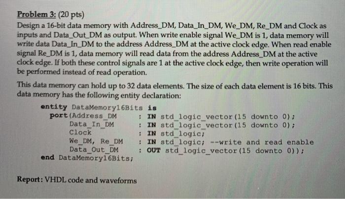
Problem 3: (20 pts) Design a 16-bit data memory with Address_DM, Data_In_DM, We_DM, Re_DM and Clock as inputs and Data_Out_DM as output. When write enable signal We_DM is 1, data memory will write data Data_In_DM to the address Address_DM at the active clock edge. When read enable signal Re_DM is 1, data memory will read data from the address Address_DM at the active clock edge. If both these control signals are 1 at the active clock edge, then write operation will be performed instead of read operation. This data memory can hold up to 32 data elements. The size of each data element is 16 bits. This data memory has the following entity declaration: entity DataMemory16Bits is port (Address DM : IN std_logic_vector (15 downto 0); Data In DM : IN std logic vector (15 downto 0); clock : IN std_logic; We_DM, Re DM : IN std_logic; --write and read enable Data Out_DM : OUT std_logic_vector (15 downto 0)); end DataMemory16Bits; Report: VHDL code and waveforms
Step by Step Solution
There are 3 Steps involved in it

Get step-by-step solutions from verified subject matter experts