

Question: Q - 1 Consider the system shown in figure - 1 . To improve the performance of the system an extra feedback loop is added
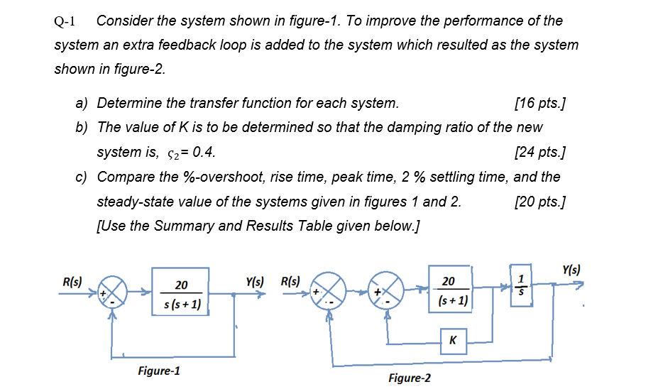
Q Consider the system shown in figure To improve the performance of the system an extra feedback loop is added to the system which resulted as the system shown in figure
a Determine the transfer function for each system.
pts
b The value of K is to be determined so that the damping ratio of the new system isvarsigma
pts
c Compare the overshoot, rise time, peak time, settling time, and the steadystate value of the systems given in figures and
pts
Use the Summary and Results Table given below.
Step by Step Solution
There are 3 Steps involved in it
1 Expert Approved Answer
Step: 1 Unlock

Question Has Been Solved by an Expert!
Get step-by-step solutions from verified subject matter experts
Step: 2 Unlock
Step: 3 Unlock