

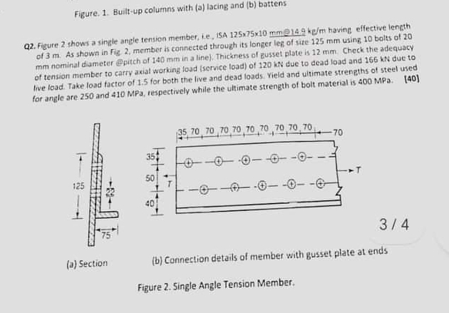
Question: Q 2 . Figure 2 shows a single angle tension member, i . e . , 1 5 A 1 2 5 7 5 1
Q Figure shows a single angle tension member, ie having of As shown in Fig, member is connected through its lenger leg of size usine nominal dameter epitch of in a line Thickness of zusset plate is Chec of tension member to carry axial working load service load of due to dead load ant live load. Take load factor of for both the live and dead loads. Yield and ultimate streng? for angle are and MPa, respectively while the ultimate strength of bolt material is
a Section
b Connection details of member with gusset plate a
Figure Single Angle Tension Member.
Use Is Mention the clause also
Figure. Builtup columns with a lacing and b battens
Q Figure shows a single angie tension member, teA having effective length of As shown in Fig. member is connected through its longer leg of site using bolts of nominal diameter Ppitch of in a line Thickness of gusset plate is Check the adequacy of tension member to carty axial working load service load of due to dead load and due to live load. Take load factor of for both the live and dead loads. Yield and witimate strengths of steel used for angle are and MPa, respectively while the ultimate strength of bolt material is MPa.
a Section
b Connection details of member with gusset plate at ends
Figure Single Angle Tension Member.
Step by Step Solution
There are 3 Steps involved in it
1 Expert Approved Answer
Step: 1 Unlock

Question Has Been Solved by an Expert!
Get step-by-step solutions from verified subject matter experts
Step: 2 Unlock
Step: 3 Unlock