

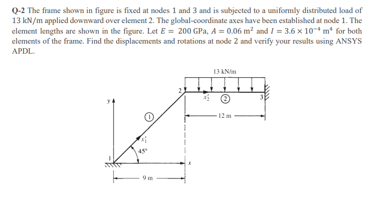
Question: Q - 2 The frame shown in figure is fixed at nodes 1 and 3 and is subjected to a uniformly distributed load of 1
Q The frame shown in figure is fixed at nodes and and is subjected to a uniformly distributed load of
applied downward over element The globalcoordinate axes have been established at node The
element lengths are shown in the figure. Let GPa, and for both
elements of the frame. Find the displacements and rotations at node and verify your results using ANSYS
APDL.
Step by Step Solution
There are 3 Steps involved in it
1 Expert Approved Answer
Step: 1 Unlock

Question Has Been Solved by an Expert!
Get step-by-step solutions from verified subject matter experts
Step: 2 Unlock
Step: 3 Unlock