

Question: Q 3 . The plane frame shown in Fig. Q 2 is now supposed to be subjected to only vertical loadings ( i . e
Q The plane frame shown in Fig. Q is now supposed to be subjected to only
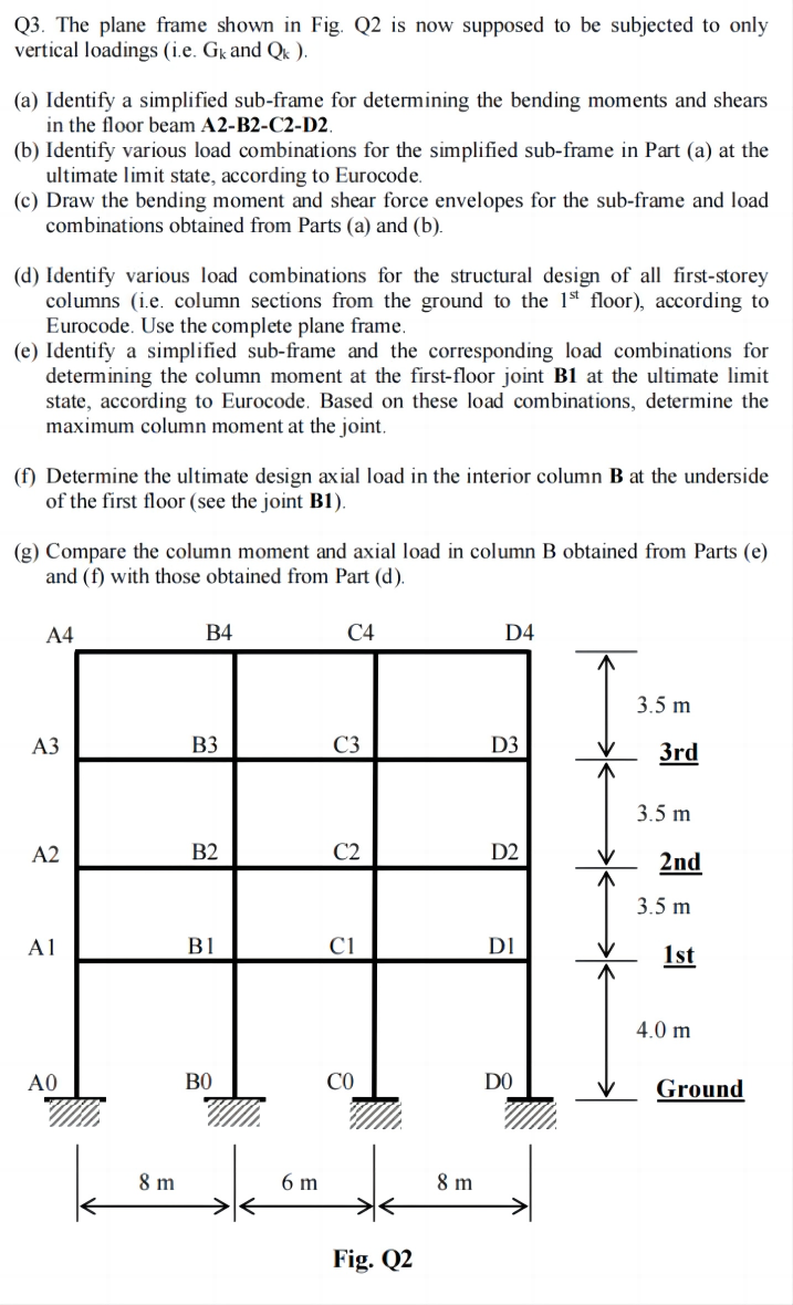
vertical loadings ie and
a Identify a simplified subframe for determining the bending moments and shears
in the floor beam ABCD
b Identify various load combinations for the simplified subframe in Part a at the
ultimate limit state, according to Eurocode.
c Draw the bending moment and shear force envelopes for the subframe and load
combinations obtained from Parts a and b
d Identify various load combinations for the structural design of all firststorey
columns ie column sections from the ground to the floor according to
Eurocode. Use the complete plane frame.
e Identify a simplified subframe and the corresponding load combinations for
determining the column moment at the firstfloor joint B at the ultimate limit
state, according to Eurocode. Based on these load combinations, determine the
maximum column moment at the joint.
f Determine the ultimate design axial load in the interior column at the underside
of the first floor see the joint B
g Compare the column moment and axial load in column B obtained from Parts e
and f with those obtained from Part d
Fig. Q
Step by Step Solution
There are 3 Steps involved in it
1 Expert Approved Answer
Step: 1 Unlock

Question Has Been Solved by an Expert!
Get step-by-step solutions from verified subject matter experts
Step: 2 Unlock
Step: 3 Unlock