

Question: Q 4 . Determine the buckling load for the frame shown above. Continuity at node 1 , m A L 1 I 1 j (
Q
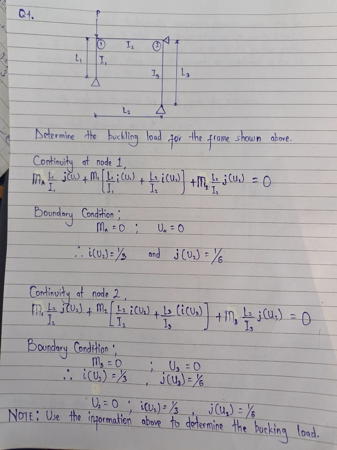
Determine the buckling load for the frame shown above.
Continuity at node
Boundary Condition:
;
: and
Continuity at node
Boundary Condition:
:
;
NOTE: Use the information above and the diagram in the text to determine the bucking load.
Step by Step Solution
There are 3 Steps involved in it
1 Expert Approved Answer
Step: 1 Unlock

Question Has Been Solved by an Expert!
Get step-by-step solutions from verified subject matter experts
Step: 2 Unlock
Step: 3 Unlock