

Question: Q 4. In the bridge type rectifier circuit shown in figure 3, the diodes are assumed to be ideal. Assume primary to secondary turn-ratio
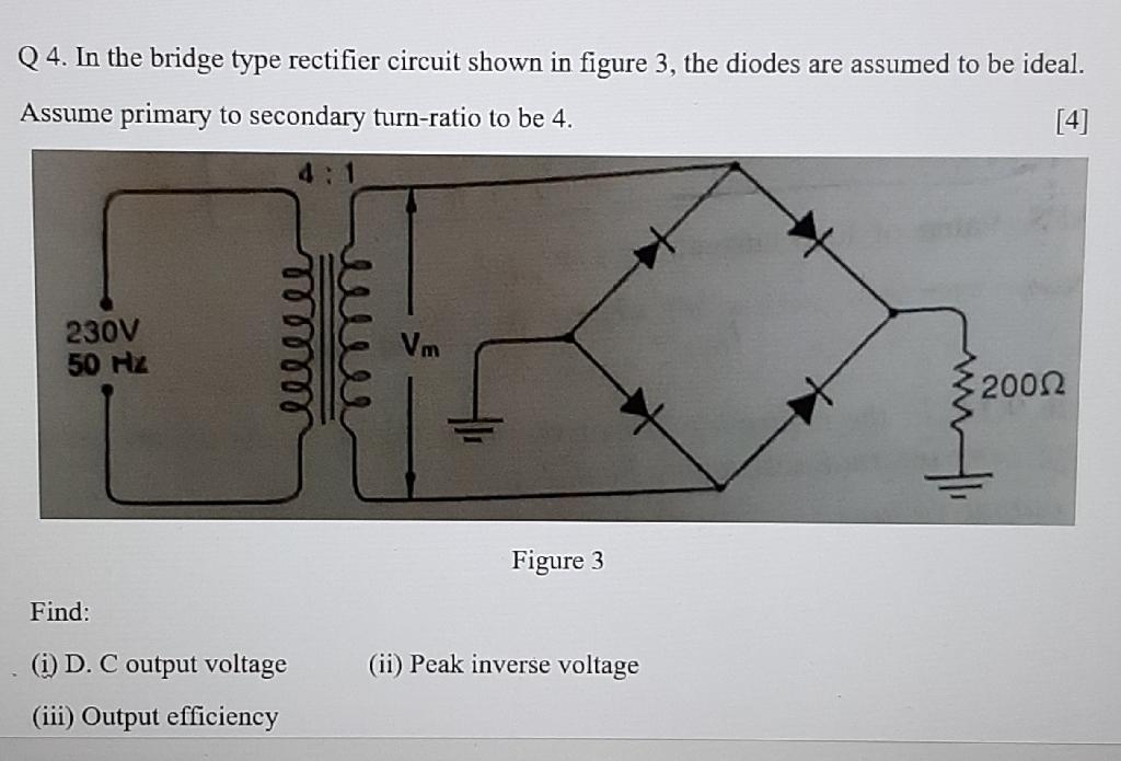
Q 4. In the bridge type rectifier circuit shown in figure 3, the diodes are assumed to be ideal. Assume primary to secondary turn-ratio to be 4. [4] 4:1 230V 50 Hz Vm 2002 Figure 3 Find: (i) D. C output voltage (ii) Peak inverse voltage (iii) Output efficiency wwee lell
Step by Step Solution
★★★★★
3.41 Rating (154 Votes )
There are 3 Steps involved in it
1 Expert Approved Answer
Step: 1 Unlock

Question Has Been Solved by an Expert!
Get step-by-step solutions from verified subject matter experts
Step: 2 Unlock
Step: 3 Unlock