

Question: Q 5 . Design a 4 - bit counter using a 4 - bit register with any needed logic gates, Logic 1 and Logic 0
Q Design a bit counter using a bit register with any needed logic gates, Logic and Logic The counter should have three synchronous control inputs. These inputs work as follows:
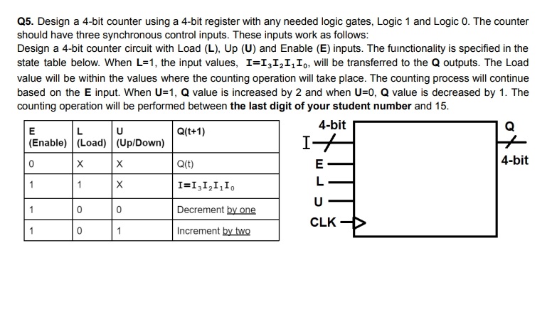
Design a bit counter circuit with Load L Up U and Enable E inputs. The functionality is specified in the state table below. When L the input values, II I I I will be transferred to the mathbfQ outputs. The Load value will be within the values where the counting operation will take place. The counting process will continue based on the mathbfE input. When mathbfUmathbfQ value is increased by and when mathbfUmathbfQ value is decreased by The counting operation will be performed between the last digit of your student number and
Step by Step Solution
There are 3 Steps involved in it
1 Expert Approved Answer
Step: 1 Unlock

Question Has Been Solved by an Expert!
Get step-by-step solutions from verified subject matter experts
Step: 2 Unlock
Step: 3 Unlock