

Question: Q ) for the control system shown in Figure a - Use the block diagram template ( on the next page ) and construct the
Q for the control system shown in Figure
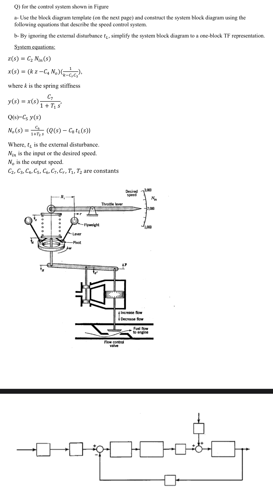
a Use the block diagram template on the next page and construct the system block diagram using the
following equations that describe the speed control system.
b By ignoring the external disturbance simplify the system block diagram to a oneblock TF representation.
System equations:
where is the spring stiffness
Where, is the external disturbance.
is the input or the desired speed.
is the output speed.
are constants
Step by Step Solution
There are 3 Steps involved in it
1 Expert Approved Answer
Step: 1 Unlock

Question Has Been Solved by an Expert!
Get step-by-step solutions from verified subject matter experts
Step: 2 Unlock
Step: 3 Unlock