

Question: (b) A sampler and a zero-order hold element were inserted into the system in Figure Ql(a) as shown in Figure Q1(b). Obtain the closed-loop pulse
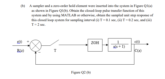
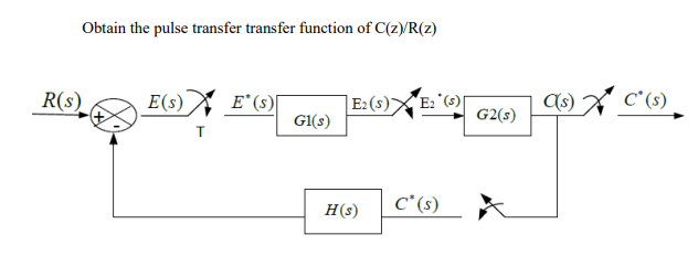
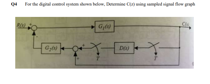
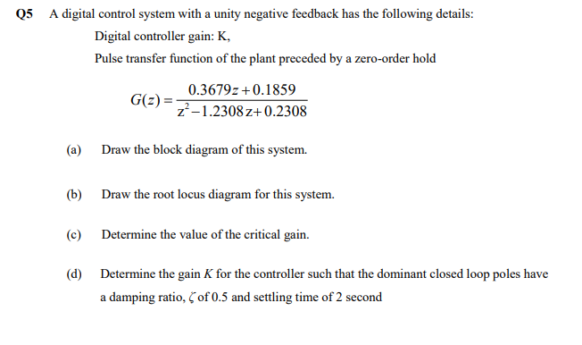
(b) A sampler and a zero-order hold element were inserted into the system in Figure Ql(a) as shown in Figure Q1(b). Obtain the closed-loop pulse transfer function of this system and by using MATLAB or otherwise, obtain the sampled unit step response of this closed loop system for sampling interval (1) T = 0.1 sec, (ii) T=0.2 sec, and (iii) T= 2 sec. + ZOH 1 c(t) s(s + 1) R(2) C(z) Figure Q2 (b) Obtain the pulse transfer transfer function of C(z)/R(z) R(S) E(s) E2() Ez (5) C'(s) EPOT Gl(s) G2) H() c* (s) Q4 For the digital control system shown below, Determine C(z) using sampled signal flow graph R(S) Cls) G;(s) 6,(s) X- Do) - T T Q5 A digital control system with a unity negative feedback has the following details: Digital controller gain: K, Pulse transfer function of the plant preceded by a zero-order hold 0.3679z+0.1859 G(z) Z-1.2308z+0.2308 (a) Draw the block diagram of this system. (b) Draw the root locus diagram for this system. (c) Determine the value of the critical gain. (d) Determine the gain K for the controller such that the dominant closed loop poles have a damping ratio, C of 0.5 and settling time of 2 second (b) A sampler and a zero-order hold element were inserted into the system in Figure Ql(a) as shown in Figure Q1(b). Obtain the closed-loop pulse transfer function of this system and by using MATLAB or otherwise, obtain the sampled unit step response of this closed loop system for sampling interval (1) T = 0.1 sec, (ii) T=0.2 sec, and (iii) T= 2 sec. + ZOH 1 c(t) s(s + 1) R(2) C(z) Figure Q2 (b) Obtain the pulse transfer transfer function of C(z)/R(z) R(S) E(s) E2() Ez (5) C'(s) EPOT Gl(s) G2) H() c* (s) Q4 For the digital control system shown below, Determine C(z) using sampled signal flow graph R(S) Cls) G;(s) 6,(s) X- Do) - T T Q5 A digital control system with a unity negative feedback has the following details: Digital controller gain: K, Pulse transfer function of the plant preceded by a zero-order hold 0.3679z+0.1859 G(z) Z-1.2308z+0.2308 (a) Draw the block diagram of this system. (b) Draw the root locus diagram for this system. (c) Determine the value of the critical gain. (d) Determine the gain K for the controller such that the dominant closed loop poles have a damping ratio, C of 0.5 and settling time of 2 second
Step by Step Solution
There are 3 Steps involved in it

Get step-by-step solutions from verified subject matter experts