

Question: Q3. The figure below represents a schematic of pipe network. A rate of 35Ls1, is pumped to feed two lines (3-4-5-6; and 2-7-8). The length
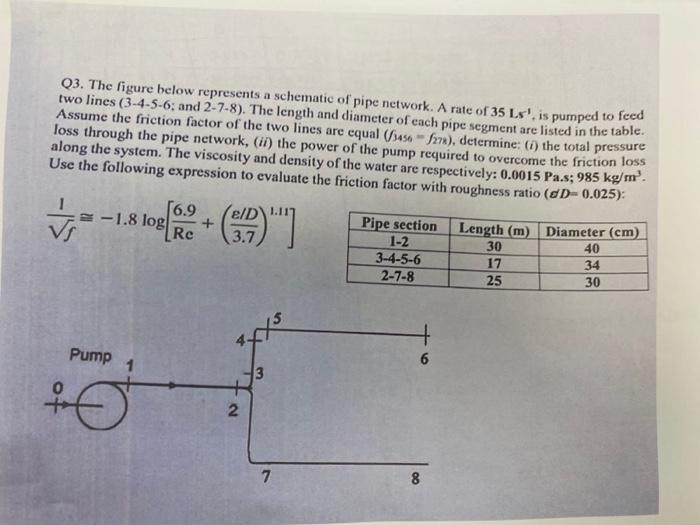
Q3. The figure below represents a schematic of pipe network. A rate of 35Ls1, is pumped to feed two lines (3-4-5-6; and 2-7-8). The length and diameter of each pipe segment are listed in the table. Assume the friction factor of the two lines are equal (/3450f272), determine: (i) the total pressure loss through the pipe network, (ii) the power of the pump required to overcome the friction loss along the system. The viscosity and density of the water are respectively: 0.0015Pas;985kg/m3. Use the following expression to evaluate the friction factor with roughness ratio (D=0.025) : f11.8log[Rc6.9+(3.7e/D)1.11] Q3. The figure below represents a schematic of pipe network. A rate of 35Ls1, is pumped to feed two lines (3-4-5-6; and 2-7-8). The length and diameter of each pipe segment are listed in the table. Assume the friction factor of the two lines are equal (/3450f272), determine: (i) the total pressure loss through the pipe network, (ii) the power of the pump required to overcome the friction loss along the system. The viscosity and density of the water are respectively: 0.0015Pas;985kg/m3. Use the following expression to evaluate the friction factor with roughness ratio (D=0.025) : f11.8log[Rc6.9+(3.7e/D)1.11]
Step by Step Solution
There are 3 Steps involved in it

Get step-by-step solutions from verified subject matter experts