

Question: Q3. The waveform generator consists of the binary synchronous integrated counter 74LS161, the 16x4-bit ROM, 4-bit-D/A conversion circuit, is shown in the figure 3 (1)
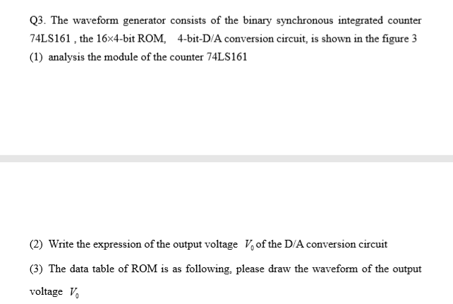
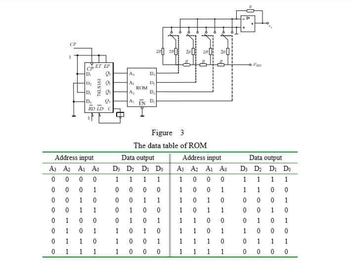
Q3. The waveform generator consists of the binary synchronous integrated counter 74LS161, the 16x4-bit ROM, 4-bit-D/A conversion circuit, is shown in the figure 3 (1) analysis the module of the counter 74LS161 (2) Write the expression of the output voltage V of the D/A conversion circuit (3) The data table of ROM is as following. please draw the waveform of the output voltage V CP ET EP D A, D D. E: 6 6 6 6 D 74LS161 D A ROM A: A EN D: D D. RD LDC Figure 3 The data table of ROM Data output Address input D D D D A: A2A AO 1 0 0 0 0 0 0 0 0 0 Data output D: D: D:D 1 1 1 1 Address input A3 A2 A1 A. 0 0 0 0 0 0 0 0 0 0 0 1 0 0 0 0 0 0 0 0 0 0 0 0 0 1 0 0 0 1 0 0 0 1 0 1 0 0 0 0 0 0 0 1 0 0 0 0 1 1 1 0 0 0 0 0 1 1 1 1 0 1 1 1 0 0 0 1 0 0 0 0 Q3. The waveform generator consists of the binary synchronous integrated counter 74LS161, the 16x4-bit ROM, 4-bit-D/A conversion circuit, is shown in the figure 3 (1) analysis the module of the counter 74LS161 (2) Write the expression of the output voltage V of the D/A conversion circuit (3) The data table of ROM is as following. please draw the waveform of the output voltage V CP ET EP D A, D D. E: 6 6 6 6 D 74LS161 D A ROM A: A EN D: D D. RD LDC Figure 3 The data table of ROM Data output Address input D D D D A: A2A AO 1 0 0 0 0 0 0 0 0 0 Data output D: D: D:D 1 1 1 1 Address input A3 A2 A1 A. 0 0 0 0 0 0 0 0 0 0 0 1 0 0 0 0 0 0 0 0 0 0 0 0 0 1 0 0 0 1 0 0 0 1 0 1 0 0 0 0 0 0 0 1 0 0 0 0 1 1 1 0 0 0 0 0 1 1 1 1 0 1 1 1 0 0 0 1 0 0 0 0
Step by Step Solution
There are 3 Steps involved in it

Get step-by-step solutions from verified subject matter experts