

Question: Question 1 ( 2 0 point ) : For the single cycle datapath figure shown in page 2 , write the state / values (
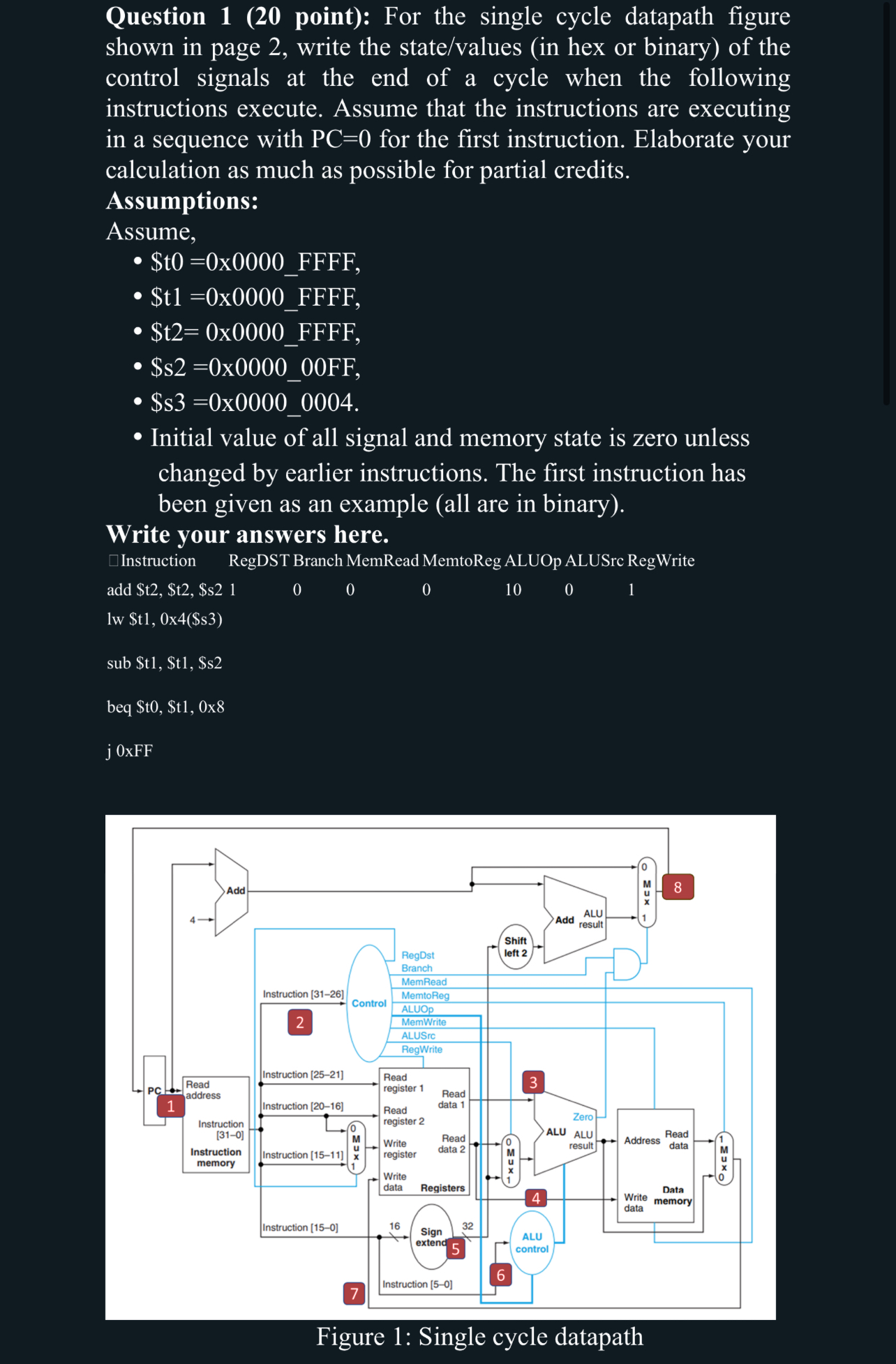
Question point: For the single cycle datapath figure shown in page write the statevalues in hex or binary of the control signals at the end of a cycle when the following instructions execute. Assume that the instructions are executing in a sequence with mathrmPC for the first instruction. Elaborate your calculation as much as possible for partial credits. Assumptions:
Assume,
$ttimes FFFF
$txFFFF
$t x F F F F
$sxFF
$sx
Initial value of all signal and memory state is zero unless changed by earlier instructions. The first instruction has been given as an example all are in binary
Write your answers here.
square Instruction RegDST Branch MemRead MemtoReg ALUOp ALUSrc RegWrite
add $t$t$s
lw $tx$s
sub $t$t$s
beq $ mathrmt$ mathrmttmathrmx
j xFF
Step by Step Solution
There are 3 Steps involved in it
1 Expert Approved Answer
Step: 1 Unlock

Question Has Been Solved by an Expert!
Get step-by-step solutions from verified subject matter experts
Step: 2 Unlock
Step: 3 Unlock